Why the standby system deserves its own mental model
The standby hydraulic system is easy to misunderstand if it is learned only as “the third pump.” It is better understood as a separate backup hydraulic circuit with its own reservoir, electric motor-driven pump, pressure-module hardware and defined aircraft functions.
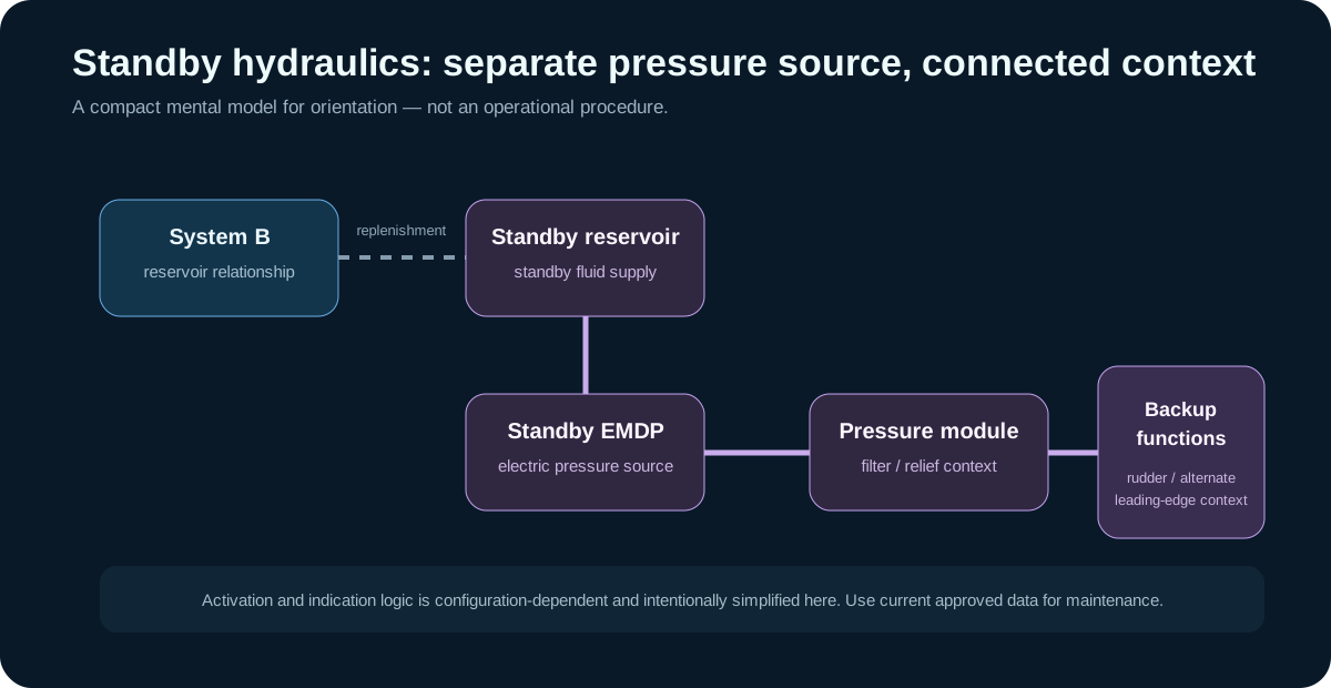
Separate pressure source
ATA 29 identifies a standby EMDP and standby pressure-module components. That means the standby circuit can create hydraulic pressure independently of the normal engine-driven sources. Its purpose is resilience: selected functions retain a hydraulic source when the normal architecture cannot provide the required capability.
The exact activation conditions belong to the aircraft control logic and approved documentation. For learning, the important distinction is that standby pressure is not simply normal System B pressure under another name.
Relationship with System B
The source states that the standby hydraulic system reservoir receives fluid from System B. Treat that as a fluid replenishment relationship, not proof that the two pressure systems are one circuit. The standby pump and pressure path remain separately identifiable.
This distinction prevents a common reasoning error: assuming that a normal System B pressure indication proves the standby system is healthy. A shared/replenishment relationship can coexist with independent pumps, valves, filters, pressure sensing and control logic.
Standby pump and pressure module
The source contents identify a standby electric motor-driven pump, case-drain filter hardware and a standby pressure module with filter and relief-valve context. Those components tell us how to frame a system problem at a high level:
- fluid available?
- electric pump able to create flow?
- pressure path controlled and filtered?
- pressure sensed and indicated correctly?
- intended backup consumer receiving the hydraulic effect?
That sequence is useful even before consulting a fault-isolation task because it separates energy generation from distribution and from indication.
Backup functions and leading-edge context
ATA 29 maintenance checks connect standby operation with alternate-flap/leading-edge-device behavior. Rather than memorizing test steps, learn the relationship: the standby hydraulic system participates in a backup path for selected flight-control functions.
This also explains why standby hydraulic work carries strong movement hazards. Supplying hydraulic power can create real actuator movement. The educational system picture should therefore always include the physical aircraft around the schematic.
Indications are not the system itself
A standby hydraulic indication is the end of a chain. The underlying state includes pump control, electrical supply, hydraulic pressure generation, pressure sensing and display logic. If an indication and physical system behavior disagree, both sides deserve evidence.
That is an especially useful lesson for modern troubleshooting: do not replace a system diagnosis with a display diagnosis. The display is evidence, not the entire fault.
What to remember
The standby system can be summarized as:
standby reservoir ? standby EMDP ? standby pressure/control hardware ? selected backup functions.
Keep the System B reservoir relationship in the background as a replenishment connection. Keep current aircraft configuration and approved maintenance data in the foreground when performing any actual check.
TechOpsBase intentionally teaches the architecture and reasoning only. It does not reproduce the AMM standby pressurization, power-removal or component-removal procedures.