Learn the pairings without losing the system logic
The quickest useful fact in B737 MAX hydraulics is also one of the easiest to reverse in memory: System A uses ENG 1 for its engine-driven pump and ELEC 2 for its electric motor-driven pump; System B uses ENG 2 and ELEC 1.
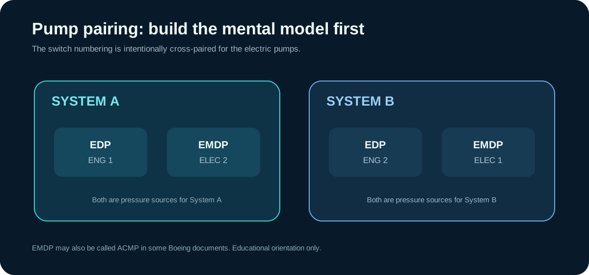
That pairing should be the beginning of the lesson, not the end. A pump can be commanded, powered and physically rotating while the hydraulic system still fails to provide the pressure/flow expected by a consumer. Likewise, a low-pressure indication is evidence that must be interpreted with the selected source, aircraft configuration and indication chain.
Engine-driven pump (EDP)
The EDP converts engine mechanical energy into hydraulic flow. In a normal system mental model, ENG 1 is associated with System A and ENG 2 with System B. The source material uses the EDP as a meaningful high-capacity pressure source in multiple maintenance contexts.
For learning purposes, the key distinction is mechanical source versus electric source. The EDP depends on the associated engine drive condition; the EMDP depends on electrical supply and control. Those different energy origins are useful when you isolate whether a hydraulic symptom is common to the fluid/distribution side or follows one pressure-generation method.
Electric motor-driven pump (EMDP / ACMP)
The electric pumps provide an independent method of creating hydraulic pressure. The AMM source uses the term EMDP, and it also notes that other Boeing documents may use ACMP for the same electric-pump concept.
Do not assume the electric pump has identical performance to an EDP in every context. ATA 29 contains maintenance situations that deliberately specify one source rather than another. That tells us something important for reasoning: source selection can be part of the evidence.
Ground hydraulic power
A ground hydraulic cart is another recognized source for maintenance. Its existence is useful for conceptual fault isolation because it can separate an installed-pump question from the downstream hydraulic system. But TechOpsBase does not provide connection or operating steps. Those belong in current approved maintenance data because wrong configuration can move aircraft systems or damage hydraulic equipment.
Reservoirs support the pumps
Reservoirs maintain the fluid supply and return environment from which the pressure sources work. The source repeatedly links pump operation with reservoir condition and fluid temperature. This reinforces a classic hydraulic principle: a healthy pump cannot perform correctly if its inlet conditions, fluid quantity or fluid condition are wrong.
Reservoir pressurization also matters. The PTU-related source material, for example, explicitly treats correct System B reservoir pressure as significant before PTU operation. The educational takeaway is not a procedural pressure value; it is that reservoir condition can be a prerequisite for another hydraulic function to behave correctly.
Pressure versus flow
A system-pressure indication is only one dimension. Hydraulic work requires both adequate pressure and sufficient flow under the demanded condition. ATA 29 includes internal-leakage checks that use flow measurement or an electrical-current-to-flow relationship on an electric pump. That is a strong teaching example: a system can look acceptable at a static pressure point yet lose effective capability when internal leakage consumes too much flow.
This is why “pressure looks normal” should not automatically end reasoning about a hydraulic performance complaint.
Pump indications are part of an evidence chain
The source includes low-pressure switches associated with the installed pumps and system indications. A LOW PRESSURE light therefore depends on more than the visual state of the switch in the flight deck. Conceptually, there is a chain:
pressure source ? hydraulic pressure at the sensing point ? pressure switch/transmitter ? electrical logic ? displayed indication.
If an indication disagrees with independent system behavior, test the assumption that the light itself proves the hydraulic state. If the aircraft behavior agrees with the indication, then the hydraulic source/distribution side becomes more significant.
Technician reasoning pattern
When a pump-related symptom appears, organize the evidence in this order:
- Which system—A, B or standby—is involved?
- Which pressure source is expected in the current configuration?
- Is the source mechanically/electrically available?
- Is reservoir condition compatible with normal pump operation?
- Do pressure and consumer behavior agree with the cockpit indication?
- Does the symptom follow one source or remain with the hydraulic system regardless of source?
That reasoning structure is deliberately generic. It makes the approved troubleshooting procedure easier to use without replacing it.