Test the platform with us. Explore real features and report anything confusing, broken or missing. Your feedback will help prepare TechOpsBase for public release.
Use the diagrams to orient yourself before opening a deep resource.
Each visual is intentionally simplified and omits task-level maintenance detail.
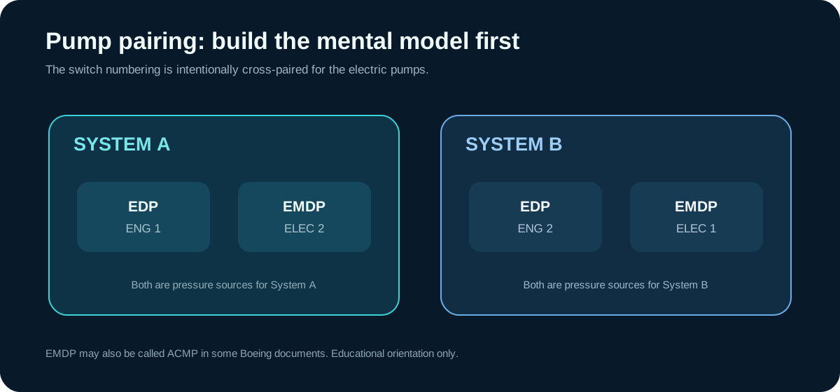
System A and B pump pairing is cross-numbered on the electric pumps.
Standby and PTU relationships are separate concepts.
The diagrams are original TechOpsBase educational artwork, not copied AMM figures.
1. System architecture
B737 MAX ATA 29 high-level hydraulic architecture
Start by separating System A, System B and standby. Then place each pressure source inside the correct system.
2. Pump pairing
B737 MAX ATA 29 pump pairing
The electric pump numbering is the memory trap: System A uses ELEC 2; System B uses ELEC 1.
3. Standby system
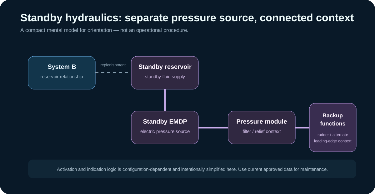
B737 MAX ATA 29 standby system concept
The dotted line represents a replenishment relationship, not pressure crossfeed. The standby circuit retains its own electric pressure source and pressure-module context.
4. PTU energy transfer
B737 MAX ATA 29 PTU concept
The PTU is easiest to remember as a motor-pump mechanical coupling. Energy can transfer while the two hydraulic fluids remain on their own sides.
These visuals are deliberately simpler than maintenance schematics. They are designed for learning, not component identification or task accomplishment.
Source-grounded learning
TechOpsBase turns controlled source material into original educational explanations. Use current approved manufacturer or operator data for aircraft work.
Source basis
Grounded in the privately supplied B737 MAX AMM Chapter 29 (D633AM101-ETH, 737-7/8/8200/9/10, May 15/2022 effective-page set). TechOpsBase wording and diagrams are original educational transformations; the proprietary source is not republished.
APPLICABILITY
Check effectivity before applying information.
Boeing 737 MAX family; exact aircraft effectivity and configuration must be confirmed in current approved data.
Operational reminder
Confirm aircraft registration, model, serial effectivity, modification status, software standard and operator procedures using current approved maintenance data.
WATCH NEXT
Best-matched creator videos
Same aircraft and ATA context is ranked first. Cross-aircraft comparisons are kept separate.
Build a durable mental model of Systems A and B, the standby system, pressure sources, reservoirs and the difference between hydraulic power removal and a true zero-energy condition.
Understand the EDP/EMDP pairings, reservoir role, pressure-source differences and why pump availability must be separated from actual system capability.
Understand the standby reservoir, electric pump, pressure module and backup-function role without confusing the standby circuit with normal Systems A or B.
Learn what the PTU transfers, why the A and B fluids do not need to mix, and how leading-edge-device, air/ground and pressure-switch logic enter the functional picture.
Use pressure, LOW PRESSURE and system behavior as separate evidence streams instead of treating one cockpit indication as a complete hydraulic diagnosis.
Connect internal leakage, contamination control, residual pressure, fluid temperature and movement hazards into one maintenance-oriented reasoning model.