Educational familiarization only. This original TechOpsBase resource explains system purpose and relationships. It does not reproduce Airbus pages, diagrams, task instructions or controlled maintenance data. Actual aircraft work requires current approved data, correct effectivity, operator procedures, authorization and supervision.
Learning objectives
- Trace the jettison flow path.
- Identify the main valve groups.
- Explain automatic stop and anti-corona protection.
1. Purpose and applicability
Fuel jettison is an optional aircraft configuration. Its purpose is to reduce aircraft weight in flight toward an acceptable landing target. Applicability must be confirmed for the individual aircraft.
2. Flow path
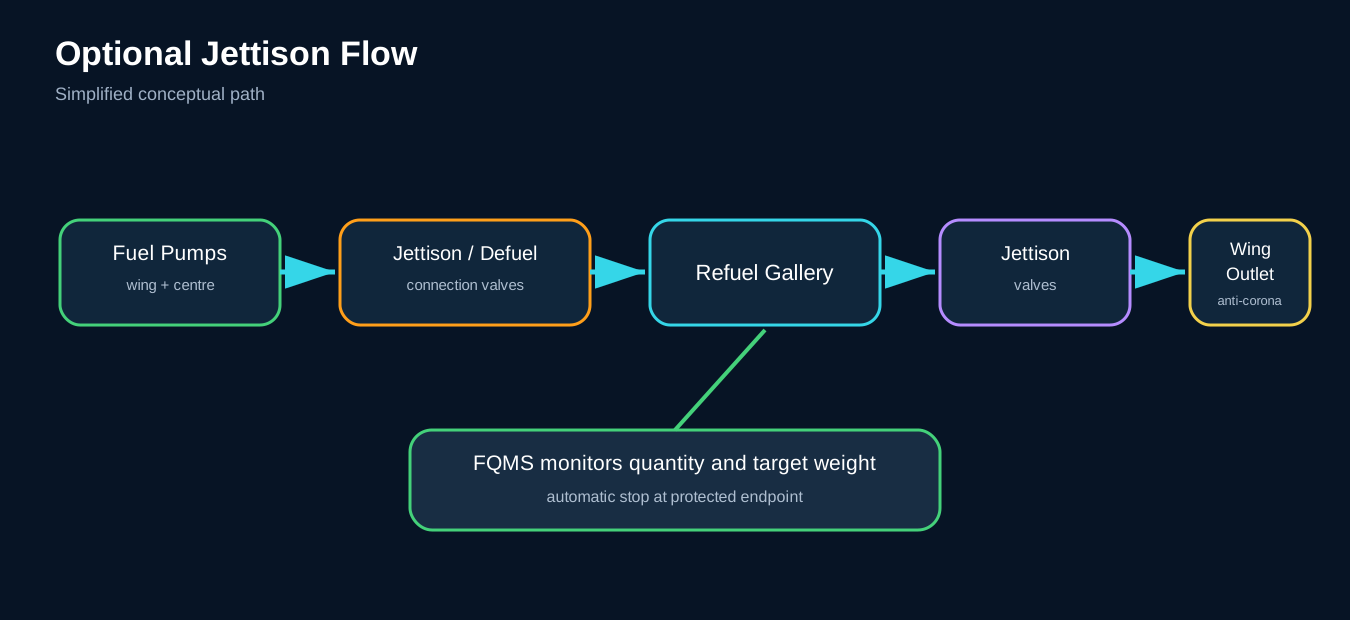
Wing and centre pumps provide pressure. Defuel/jettison valves connect wing feed pressure to the refuel gallery, while centre-tank jettison valves connect centre pumps. Jettison valves then route gallery fuel to wing discharge pipes.
3. Discharge protection
The outlet position keeps discharged fuel away from aircraft structure. Anti-corona nozzles reduce the likelihood of electrical discharge igniting fuel vapour at the outlet.
4. Control
The crew arms and activates jettison through guarded controls. FQMS logic monitors fuel quantity and aircraft-weight target and stops jettison at the defined endpoint or minimum fuel protection. Manual deselection also stops the process.
5. Maintenance awareness
Jettison shares the refuel gallery and valve architecture. Troubleshooting must consider pump pressure, gallery configuration, valve feedback, quantity calculation and aircraft option status.
6. Option status and purpose
Not every A350 has the jettison option. The aircraft configuration and effectivity must be confirmed before interpreting controls, valves or maintenance messages.
The purpose is to reduce aircraft weight in flight toward a target suitable for landing. Jettison is not used for routine fuel balancing or tank maintenance.
7. Shared architecture
Jettison uses existing fuel pumps and much of the refuel gallery.
Wing feed pumps or centre pumps provide pressure. Defuel/jettison valves connect pressure sources to the gallery. Dedicated jettison valves route the gallery to left and right discharge pipes.
Sharing hardware reduces system weight but creates functional interaction with refuel, defuel and transfer.
8. Discharge outlets
Fuel exits through outlets near the wing tips or approved outboard locations. The geometry keeps the fuel stream away from the aircraft surface and engine ingestion zones.
Anti-corona features reduce electrical-discharge risk at the outlet. Bonding and approved outlet condition are part of ignition prevention.
9. Control sequence
A simplified sequence is:
- Crew arms the jettison function.
- Target or landing-weight information is available.
- FQMS validates aircraft configuration.
- Required pumps and valves are commanded.
- Fuel discharges through both sides.
- FQMS monitors total and tank quantities.
- The system stops at the target, protective minimum or fault.
- Valves return to the safe configuration.
Manual deselection can stop the process.
10. Quantity and target logic
The stop point depends on accurate quantity calculation. FQMS also protects a minimum remaining fuel quantity and monitors tank distribution.
A quantity fault can therefore inhibit jettison, cause an early stop or require an alternate approved strategy.
11. Tank sequencing and balance
The system must reduce weight while preserving lateral balance and engine supply.
Valve and pump sequencing prevents one tank from emptying in a way that creates unacceptable imbalance or exposes pump inlets. Centre and wing sources are managed according to the installed logic.
12. Interaction with wing transfer
Manual wing-to-centre transfer and jettison use some of the same inlet and gallery paths.
FQMS inhibits jettison while manual transfer is selected. Wing inlet valves are commanded to prevent recirculation or wing overflow during jettison.
13. Failure modes
One jettison valve fails closed
Discharge rate or symmetry is reduced. The system can stop and alert depending on logic.
Valve fails open
Uncommanded fuel loss is possible if pump pressure reaches the gallery. Isolation and indication are critical.
Pump pressure unavailable
Jettison rate drops or the function becomes unavailable.
Quantity computation invalid
Automatic target control may be unavailable.
Outlet damaged or blocked
Backpressure, leakage or unsafe discharge pattern can occur.
Position indication disagrees
The system may stop or alert even if flow continues through another path.
14. Maintenance awareness
Jettison maintenance affects:
- Refuel gallery integrity
- Pump and valve operation
- Outlet bonding
- Anti-corona devices
- Drainage and leakage
- FQMS quantity logic
- Aircraft option configuration
- Functional tests
A test must use the approved method to avoid unintended fuel discharge or environmental hazard.
15. Diagnostic model
For a jettison fault:
- Confirm the aircraft has the option.
- Confirm arm/start command and target.
- Check quantity-data validity.
- Check pump pressure.
- Check defuel/jettison valve position.
- Check dedicated jettison valve position.
- Compare left/right discharge evidence where approved.
- Review inhibits from wing transfer or other configuration.
- Follow current fault-isolation data.
16. Jettison rate
Discharge rate depends on:
- Number of operating pumps
- Available pump pressure
- Valve configuration
- Fuel quantity and tank source
- Discharge-pipe condition
- Aircraft altitude and external pressure
- Symmetry between left and right outlets
The crew display can provide estimated time or progress. Maintenance should not use a generic rate as a pass/fail limit; current aircraft data and test conditions control.
17. Automatic termination layers
Termination is protected by more than one condition:
- Reaching the selected target
- Reaching a protected minimum quantity
- Quantity-data invalidity
- Valve or pump fault
- Manual stop
- Configuration inhibit
The system should fail toward stopping uncontrolled fuel loss.
18. Uncommanded jettison protection
An open discharge valve alone does not cause flow unless fuel pressure reaches the gallery. Conversely, pump pressure with a closed outlet does not discharge fuel.
Safety depends on the combination of pump and valve commands, independent position feedback and logic that prevents unintended simultaneous paths.
19. Environmental and ground-test boundary
Fuel discharge creates fire, environmental and airport hazards. Functional testing must avoid releasing fuel unless the approved procedure and location explicitly allow it.
Tests can use electrical simulation, valve position checks or controlled ground equipment depending on the task. The public resource must not invent a test method.
20. Outlet inspection awareness
The outlet and anti-corona feature are exposed to weather, contamination and physical damage.
Inspection concepts include:
- Outlet security and alignment
- Bonding condition
- Blockage
- Damage to anti-corona features
- Leakage at pipe joints
- Evidence of unauthorized repair
The outlet is both a fluid component and an ignition-prevention component.
Key takeaways
- Jettison is optional and configuration-dependent.
- It reuses pumps and the refuel gallery.
- FQMS quantity and weight logic controls automatic stopping.
- Anti-corona outlets are ignition-prevention features.
Approved-data boundary
This resource is a study aid. It must not be used to determine maintenance steps, limits, dispatch status, component removal criteria or aircraft configuration. Use the current applicable AMM, TSM/FIM, WDM, IPC, CMM, ALS/CDCCL data, operator procedures and task cards for real work.