Educational familiarization only. This original TechOpsBase resource explains system purpose and relationships. It does not reproduce Airbus pages, diagrams, task instructions or controlled maintenance data. Actual aircraft work requires current approved data, correct effectivity, operator procedures, authorization and supervision.
Learning objectives
- Explain the fuel-vapour combustion triangle.
- Define the maintenance purpose of a CDCCL.
- Identify common ignition-source pathways.
- Recognize work that can unintentionally defeat a safety feature.
1. Why tank safety is different
Liquid fuel does not explode by itself. The tank ullage can become flammable when fuel vapour and oxygen exist in a suitable concentration and an ignition source supplies enough energy. The safety strategy is therefore to control both the flammable environment and possible ignition energy.

2. CDCCL meaning
A Critical Design Configuration Control Limitation protects a feature that is necessary to prevent an unsafe ignition condition. The limitation preserves the approved design during maintenance, modification or repair.
Typical controlled characteristics can include:
- Wire routing and separation
- Bonding paths and resistance
- Connector type and installation
- Pump or probe configuration
- Shielding and grounding
- Fastener, sealant or material selection
- Clearances from heat or electrical sources
A technician must not treat these details as optional workmanship preferences. The exact requirement comes from the current Fuel Airworthiness Limitations and referenced approved instructions.
3. Main ignition pathways
Four useful categories are:
- Electrical arcing: damaged wiring, connectors, ground faults or induced energy.
- Filament heating: conductive debris or fine wire heated by current.
- Friction sparking: foreign material contacting rotating pump parts.
- Hot surfaces: nearby equipment or ducts heating tank structure or fuel vapour.
Lightning and electrostatic effects are controlled through structural conduction, bonding, shielding and discharge design.
4. Maintenance actions that need special discipline
High-risk activities include tank entry, wiring repair, probe replacement, pump work, connector work, bonding restoration, structural repair near tanks and any alteration that changes separation or material.
The correct mindset is:
- Identify whether the task references an airworthiness limitation or CDCCL.
- Preserve the exact configuration.
- Use approved consumables, tooling and test methods.
- Record required measurements or inspections.
- Prevent contamination and foreign objects.
- Confirm the independent inspection or sign-off requirement.
5. What a visual inspection cannot prove
A clean-looking installation may still have excessive bond resistance, incorrect wire separation, wrong hardware or a hidden connector defect. Safety features often require measured or documented verification rather than appearance alone.
6. Regulatory and design background
Fuel-tank safety requirements were strengthened after serious accidents showed that a transport-aircraft fuel tank can become hazardous when a flammable ullage and an ignition source exist together. Design review and continued-airworthiness requirements therefore address both the probability of ignition and the ability of maintenance to preserve the approved safety features.
A CDCCL is not a routine inspection interval. It is a configuration limitation. It states that a particular design characteristic must remain within its approved condition because changing it could increase ignition risk. The controlled feature may be visible, such as a bonding jumper, or embedded in installation details such as wire separation, connector type or material.
Fuel Airworthiness Limitations gather mandatory continued-airworthiness information. The public study lesson should teach the concept, while the current operator-controlled ALS and referenced maintenance data provide the actual requirement.
7. Combustion-triangle reasoning
An explosion requires:
- A flammable fuel-vapour mixture
- Oxygen
- Sufficient ignition energy
Liquid fuel itself is not the complete hazard. The ullage above the fuel can contain vapour whose flammability changes with temperature, pressure, fuel type and ventilation. Removing every trace of vapour is not normally practical, so the design concentrates heavily on preventing ignition energy and controlling the tank environment.
The difference between flash point and auto-ignition temperature matters conceptually. Flash point describes the temperature at which a liquid produces enough vapour to ignite when an external ignition source is introduced. Auto-ignition occurs when the mixture ignites from temperature alone. Maintenance around fuel tanks must therefore control sparks, arcs, hot surfaces and frictional heating.
8. Lightning and static-current paths
The aircraft structure must carry lightning and static current around or through the fuel-tank region without producing an ignition source in the ullage. Protection uses multiple conductive paths, controlled joints, fasteners, bonding and shielding.
On a composite aircraft, the current path is more engineered than a simple metal-skin assumption. Conductive layers, metallic fittings, bonding straps and structural interfaces work together. A repair that changes fastener type, surface treatment, sealant, conductive mesh or joint preparation can affect the current path even when the repair looks structurally acceptable.
Bonding provides low-resistance paths between components and structure. It helps prevent voltage difference and arcing. Some bonds are redundant; loss of one path may have no immediate operational effect, which makes the failure hidden. That does not make the bond unimportant. It means scheduled checks and correct restoration are the detection method.
9. Wiring and electrical-energy control
Fuel-system wiring can carry measurement signals, valve commands, pump power and position feedback. The ignition risk depends on both available energy and the location of a fault.
Protection principles include:
- Separation of higher-energy wiring from intrinsically safe circuits
- Shielding and grounding
- Controlled routing through tank boundaries
- Approved connectors and backshells
- Chafing protection and clamp spacing
- Ground-fault detection for pump power
- Electrical isolation during maintenance
- Lightning and transient protection
An apparently small routing change can defeat separation or allow chafing against structure. Unapproved splices, altered shields or incorrect connector hardware can change circuit energy or fault behavior.
10. In-tank equipment
Pumps, valves, probes, pressure switches and wiring installed in or near the tank are designed to avoid becoming an ignition source.
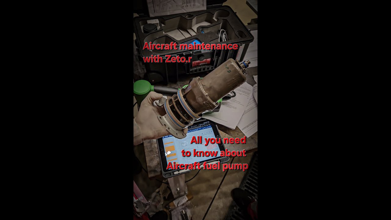
Pump safety depends on more than electrical insulation. Internal clearances, bearings, cooling, lubrication by fuel, ground-fault protection, approved parts and freedom from foreign objects all matter. A pump running dry or with damaged internal parts can create heat or friction. Maintenance instructions and component limitations protect these design assumptions.
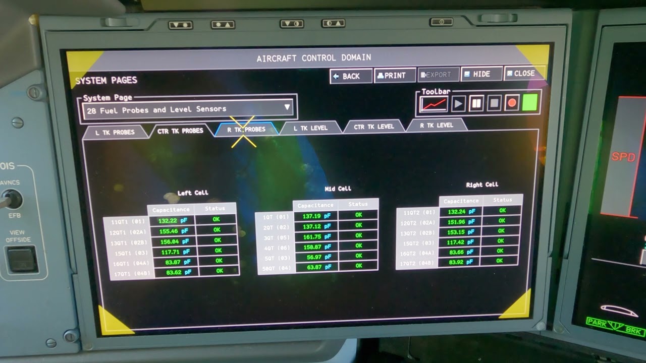
Quantity-indicating probes use low-energy circuits. The safety of the circuit depends on the complete path, including wiring, concentrators, connectors and separation from higher-energy sources. Replacing a probe correctly but routing its cable incorrectly can still undermine the design.
11. Fuel leaks and adjacent ignition sources
A fuel leak becomes more hazardous when it reaches electrical equipment, hot surfaces or enclosed areas. The design therefore uses pipe shrouds, drainage, ventilation, sealed connectors, explosion-resistant equipment and controlled routing.
Adjacent heat sources can include bleed-air ducts, electrical power equipment, brakes, engines and APU zones. Overheat detection and thermal barriers reduce the likelihood that tank structure or leaked fuel reaches an unsafe temperature.
Drain paths must remain open. A blocked drain may be hidden until another failure causes leakage. This is a classic combination of latent conditions: the primary pipe leak and the unavailable drain path together create a greater hazard than either condition alone.
12. Fuel Tank Inerting System relationship
Where fitted and active, the inerting system reduces oxygen concentration in the tank ullage. It adds another barrier but does not remove the need for ignition-source prevention. Bonding, wiring control, pump protection and CDCCLs remain necessary because inerting effectiveness varies by phase, tank condition and system availability.
The correct mental model is layered defense, not substitution.
13. Maintenance configuration control
A good CDCCL review asks:
- What safety function is being preserved?
- Which installation dimensions, materials or electrical properties are controlled?
- Is an independent inspection required?
- Are measured values or test results required?
- Does the work affect adjacent wiring or bonding?
- Is the replacement part exactly approved for the effectivity?
- Does a structural repair change lightning-current paths?
- Does the task require special cleaning or foreign-object control?
The answer must come from current approved data. Generic workmanship standards are not enough when a specific limitation applies.
14. Tank-entry awareness
Fuel-tank entry involves confined-space, flammability, toxicity, ventilation, rescue and electrical-isolation hazards. The public resource should not reproduce entry procedures. The educational points are:
- The tank must be placed in the approved safe condition.
- Fuel-system, flap/slat and related electrical sources may require isolation.
- Ventilation and atmospheric monitoring must be controlled.
- Tools, lighting, clothing and communications must be suitable.
- A rescue plan and standby personnel may be required.
- Local law and operator procedures can add requirements.
Tank entry is not simply an access task with extra personal protective equipment. It is a controlled operation.
15. Hidden failures and maintenance-program logic
Many ignition-prevention failures are not evident to the crew:
- A degraded bonding path
- A blocked drain
- Incorrect wiring separation
- Damage to a shield
- Loss of one redundant protection path
- Internal wear that could create frictional heat
MSG-3 analysis identifies these hidden functions and determines whether a maintenance task is needed to reveal the condition before it combines with another failure. The educational lesson is that “no cockpit message” does not mean “no safety significance.”
16. Technician review scenario
Imagine a harness near a fuel-tank boundary has been replaced. A complete safety review is broader than continuity:
- Confirm part number and effectivity.
- Confirm routing, separation and clamps.
- Confirm shielding and grounding restoration.
- Confirm connector and backshell configuration.
- Check adjacent bonds and structural repair status.
- Verify no foreign material or sharp edge remains.
- Complete required inspections and measurements.
- Record the controlled configuration.
This scenario shows why fuel-tank safety is a system property maintained by disciplined installation.
Key takeaways
- Fuel-tank safety is based on layered prevention.
- CDCCLs preserve ignition-prevention design features through the aircraft life.
- Wiring, bonding, materials and installation geometry can be safety-critical.
- Never substitute memory or general practice for the current controlled requirement.
Approved-data boundary
This resource is a study aid. It must not be used to determine maintenance steps, limits, dispatch status, component removal criteria or aircraft configuration. Use the current applicable AMM, TSM/FIM, WDM, IPC, CMM, ALS/CDCCL data, operator procedures and task cards for real work.