Educational familiarization only. This original TechOpsBase resource explains system purpose and relationships. It does not reproduce Airbus pages, diagrams, task instructions or controlled maintenance data. Actual aircraft work requires current approved data, correct effectivity, operator procedures, authorization and supervision.
Resource profile
- Aircraft: Airbus A350 family
- ATA chapter: 28 - Fuel
- Audience: Students, junior technicians and working professionals
- Level: Intermediate familiarization
- Source basis: Privately supplied 2013-2014 manufacturer training and MSG-3 material
- Technical status: Draft pending technical review
- Estimated study time: 45-60 minutes
Learning objectives
After completing this overview, the learner should be able to:
- Describe the three main fuel-storage tanks and the two surge tanks.
- Explain how the FQMS measures, manages and monitors fuel-system functions.
- Trace normal engine and APU fuel-feed paths.
- Distinguish crossfeed, wing transfer, refuel/defuel and jettison functions.
- Explain why ignition prevention, bonding, wiring segregation and CDCCLs are critical.
- Identify how drainage, scavenge and venting protect fuel quality and tank structure.
1. One connected system
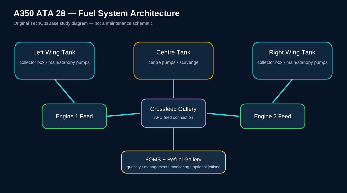
The A350 fuel system is not just a set of tanks and pumps. It is a connected architecture with five major jobs:
- Store fuel in the left wing, centre and right wing tanks.
- Protect the tank structure and fuel vapour space through venting, ignition prevention and controlled configuration.
- Measure and manage quantity, temperature, level, imbalance, centre of gravity and fuel movement.
- Supply the engines and APU with adequate pressure and isolation capability.
- Move or remove fuel through refuel, defuel, transfer and optional jettison functions.
2. Storage and tank arrangement
The aircraft uses a left wing tank, a centre tank and a right wing tank. Each wing tank contains a collector-box area that helps keep fuel around the engine-feed pump inlets during manoeuvres. Clack valves support inward flow into the collector box and oppose unwanted outward movement.
The centre tank extends through the centre wing box and inner-wing areas. The wing tanks are generally retained until later in the normal usage sequence because wing fuel provides structural bending relief.
Outboard surge tanks collect fuel displaced during manoeuvres or overflow conditions. Their vent path also connects the fuel tanks to atmosphere while protecting against flame propagation and excessive differential pressure.
3. Safety is part of the architecture
Fuel vapour becomes hazardous when fuel vapour, oxygen and a sufficient ignition source exist together. A350 fuel-system safety therefore depends on design features and maintenance controls working together:
- Lightning and static-current paths
- Bonding and grounding
- Intrinsically safe quantity-indicating circuits
- Ground-fault protection for pumps and associated wiring
- Controlled routing and separation of electrical wiring
- Leak containment and drainage
- Fuel Airworthiness Limitations and CDCCLs
A repair that appears mechanically acceptable can still be unsafe if it changes bonding, separation, shielding, material, fastener or installation features that were part of the approved ignition-prevention design.
4. Measurement and management
The Fuel Quantity and Management System has three broad roles:
- Measurement: quantity, temperature, level, imbalance and centre-of-gravity information.
- Management: commands to pumps and valves for refuel, defuel, transfer and optional jettison.
- Monitoring: component status, fault detection and built-in tests.
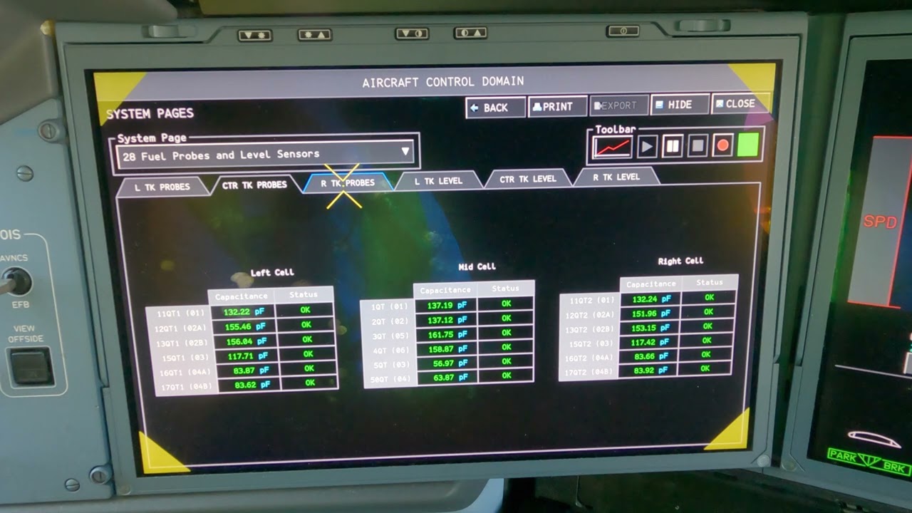
Capacitance probes, temperature/level probes, point-level sensors and fuel-properties measurements feed tank-wall concentrators. Fuel applications in redundant computing channels turn those inputs into usable quantities, control decisions and indications.
5. Engine and APU supply
Normal engine supply can come from centre-tank or wing-tank pumps. Centre-tank pumps have higher delivery pressure and therefore take precedence when available. Wing tanks have main and standby pump capability. Crossfeed valves can connect the left and right engine-feed galleries when required.
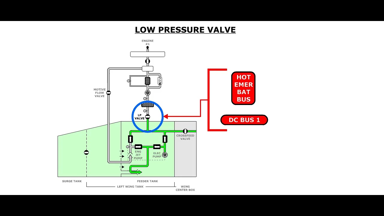
Each engine has a low-pressure shutoff valve that isolates the aircraft fuel system from the engine for shutdown or fire isolation. The APU can receive fuel from the engine-feed gallery or from its dedicated electric pump when gallery pressure is insufficient.
6. Ground and in-flight fuel movement
Refuel and defuel operations use the refuel gallery, tank inlet valves, coupling isolation and integrated control. Wing transfer is a manually selected gravity-transfer/recovery function that can route wing fuel toward the centre tank under suitable head conditions. The optional jettison system uses pumps, gallery valves and wing discharge outlets to reduce aircraft weight in flight.
These functions share equipment and logic. A fault or configuration in one area can therefore influence another; for example, the refuel gallery is also used by pressure defuel and optional jettison.
7. Water, drainage and fuel condition
Water can enter fuel through uplifted fuel or condensation. The system uses low-point drains and jet-pump scavenge arrangements to reduce accumulation. Pipe shrouds and drain masts provide a controlled path for leakage from selected fuel-feed lines, keeping fuel away from occupied or vulnerable structure and making leakage visible to maintenance personnel.
8. Maintenance reasoning model
For any ATA 28 fault, work through this sequence:
- Tank and source: Which tank or gallery should be supplying fuel?
- Command: Which FQMS, cockpit, fire or ground command applies?
- Power: Which electrical source, SSPC, RCCB, FFSU or control channel is required?
- Valve/pump position: Is the component commanded, powered and mechanically in the expected state?
- Pressure/level evidence: Do independent pressure, quantity and level indications agree?
- Safety boundary: Does the work affect a CDCCL, bonding, wiring separation, tank entry or ignition-prevention feature?
- Approved data: What does current applicable fault-isolation and maintenance data require next?
9. Architecture by functional layer
A useful way to study ATA 28 is to separate the system into functional layers and then reconnect them.
Containment layer
The containment layer is the aircraft structure that forms the left wing tank, centre tank, right wing tank and the two outboard vent/surge tanks. Tank boundaries, access panels, seals, structural penetrations and drain paths are all part of the fuel system. They are not merely airframe features around the fuel equipment. The containment design must retain fuel, tolerate normal pressure changes, limit loss after defined damage cases and allow controlled access for inspection and maintenance.
Fluid-mechanical layer
This layer contains the pumps, galleries, valves, collector boxes, clack valves, jet pumps, refuel lines, vent pipes and drain paths. It determines where fuel can physically move. A commanded valve position or pump selection is meaningful only when the fluid path, pressure relationship and tank head support the intended flow.
Electrical power layer
Pumps, actuators, processors, concentrators and panels depend on several electrical sources. Some components use independent supplies so an essential isolation or feed function remains available in a degraded electrical configuration. Centre-tank pump power includes ground-fault protection because electrical leakage near a fuel tank can become an ignition concern.
Control and computation layer
The FQMS combines quantity calculation, automatic fuel management, refuel control, transfer logic, jettison logic where installed, fault monitoring and indication support. Other aircraft systems provide configuration and flight-phase information. The FQMS does not create fuel flow by itself; it commands and supervises the fluid-mechanical equipment.
Indication and maintenance layer
The flight deck, Integrated Refuel Panel and maintenance systems present quantity, pump, valve and fault information. A displayed state is the end of a chain: sensor or switch, wiring, data concentration, software logic and presentation. Troubleshooting must keep the entire chain in view.

10. Normal fuel-use sequence as a pressure-management problem
The normal sequence is easier to understand when viewed as a competition between available pressure sources.
Centre-tank pumps are designed to provide higher delivery pressure than the wing-tank feed pumps. When centre fuel is available and the centre pumps are permitted to operate, centre fuel therefore feeds the engines in preference to wing fuel. This allows the centre tank to be emptied while wing fuel remains available for structural bending relief.
Wing tanks provide their own main and standby feed sources. The collector boxes help maintain a stable local supply around the pump inlets during manoeuvres. If a normal pressure source is lost, standby capability, crossfeed configuration or gravity-feed capability can preserve some level of engine supply depending on the exact failure and aircraft condition.
The sequence is not based only on tank quantity. It is affected by:
- Pump selections and automatic commands
- Available electrical power
- Pump outlet pressure
- Crossfeed-valve position
- Flight phase and flap/slat configuration
- Tank empty or low-level determination
- Engine demand
- Fault and protection logic
During selected critical flight phases, centre-tank pump operation is inhibited or stopped by automatic logic. The training value is the relationship: flight-phase information can deliberately change the preferred fuel source. The exact current conditions must always be checked in approved data.
11. Tank architecture and fuel availability
Each wing tank contains a main-cell area and a collector-box area. Gravity flow through clack valves lets fuel enter the collector box while limiting outward movement. This keeps the pump inlets covered during acceleration, climb, descent and lateral manoeuvres.
The centre tank is structurally divided into cells by the centre wing-box and inner-wing arrangement. Drain holes and low-point collection paths allow water and residual fuel to move toward locations where drain valves or scavenge jet pumps can act.
Fuel quantity in a tank is not automatically equal to usable fuel. Fuel can become trapped when:
- Both pressure sources associated with a wing tank are unavailable
- A valve or gallery configuration blocks the intended path
- A transfer function is unavailable
- Tank attitude and fuel head do not support gravity flow
- A quantity indication is misleading
- A venting problem restricts normal pressure equalization
That is why the fuel display can distinguish between fuel on board and fuel availability.
12. Venting and structural pressure protection
Fuel volume and ullage volume change during refuel, defuel, transfer, climb, descent and temperature variation. The vent system lets air move into and out of the tanks so the tank structure is not exposed to damaging pressure differential.
Vent pipes connect the storage tanks to the outboard vent/surge tanks. Each surge tank communicates with atmosphere through a NACA-type intake and flame-arresting feature. The design can create light positive pressure in flight while preventing flame propagation from outside into the tank vent network. An overpressure protector provides an alternative relief path if the normal atmospheric opening becomes blocked.
Float-operated vent valves and high-level vent locations help preserve ventilation across aircraft attitudes and fuel levels. The vent system therefore affects tank structure, refuel performance, transfer flow and quantity behavior.
13. Quantity measurement is a calculated result
The displayed mass of fuel is not a direct reading from one sensor. It is the result of multiple inputs and calculations.
The measurement chain includes:
- Capacitance-type tank units distributed through the tank volume
- Temperature sensing
- Point-level or high-level sensing
- Tank geometry
- Aircraft attitude or acceleration-related compensation
- Fuel-density and permittivity information
- Data concentration near the tanks
- Redundant fuel applications hosted in aircraft computers
Capacitance changes with the amount and dielectric properties of the fuel surrounding each probe. The system combines probe information with tank shape and fuel properties to calculate volume and mass. A quantity disagreement can therefore originate from sensing, fuel properties, wiring, data concentration, computation or configuration—not only from a failed probe.
An independent or lower-accuracy quantity function can support dispatch under defined conditions. Its purpose is degraded capability, not confirmation that the primary calculation is healthy.
14. Automatic management functions
The FQMS supports several automatic functions:
- Centre-tank pump management
- Refuel valve sequencing and preselected quantity control
- High-level and overflow protection interfaces
- Defuel and ground-transfer control
- Manual wing-transfer monitoring
- Optional jettison control and stopping logic
- Quantity, imbalance and trapped-fuel monitoring
- Status and fault reporting
Automatic management depends on independent evidence. For example, a refuel target is calculated from quantity inputs, but tank high-level protection provides another layer against overfill. A pump command can be issued by software, but pressure and electrical feedback are needed to determine whether useful output exists.
15. Engine-feed architecture
Each side has a feed gallery leading toward its engine LP shutoff valve. The wing tank provides main and standby pumps. Centre-tank pumps connect into the feed architecture at higher delivery pressure. Crossfeed valves can join the left and right galleries.
When crossfeed valves are closed, the left and right sides remain independent. Opening a crossfeed path allows one side or a centre-tank source to support both engines, subject to pressure and configuration. Two crossfeed valves provide redundancy and remain relevant in degraded electrical configurations.
The engine LP shutoff valve is the aircraft-side isolation point. It responds to normal engine-master control and to fire isolation. The fire command has priority because the purpose is to stop fuel flow into an engine or pylon fire zone.
16. APU feed architecture
The APU feed is connected to the engine-feed gallery. If gallery pressure is available, it can supply the APU. A dedicated electric APU pump provides pressure when gallery pressure is inadequate, including relevant ground or battery-start conditions.
The APU line includes isolation and low-pressure valves, pressure sensing, thermal relief and a shrouded drain arrangement. Later configurations include line-break detection so damage can command automatic isolation. The APU system illustrates a recurring ATA 28 principle: a fuel path is supported by multiple protective functions—pressure source redundancy, valve isolation, leak containment, line-damage detection and indication.
17. Refuel, defuel and ground transfer
Pressure refuel brings fuel through a coupling, isolation valve and common refuel gallery. Tank inlet valves direct fuel to the selected tanks. The FQMS compares the target load with calculated tank quantities and controls the valves to achieve the requested distribution.
Defuel can use aircraft pumps to pressure fuel toward external equipment or external suction applied to the refuel gallery. Ground transfer uses selected pumps and valves to move fuel between tanks for maintenance or loading purposes. These modes share hardware, so an incorrect valve configuration can affect more than one function.
The Integrated Refuel Panel is the ground operator’s main interface. It provides quantities, selections, status and fault information. The panel is part of the control chain, not an independent fuel computer.
18. Wing transfer and trapped-fuel recovery
Normal A350 fuel management does not depend on routine in-flight transfer between tanks. Manual wing-to-centre transfer exists mainly to recover fuel trapped in a wing tank after loss of both associated feed-pump pressure sources.
The function opens selected wing and centre inlet valves. Flow is produced by gravity and fuel-height difference rather than a dedicated transfer pump. Because head determines direction, the same open path can permit reverse movement when the centre-tank fuel level is higher. This is why tank quantity trend and configuration must be monitored rather than assuming the selected direction guarantees actual flow.
19. Optional jettison
Where installed, jettison uses existing pump pressure and much of the refuel-gallery architecture. Defuel/jettison and dedicated jettison valves route fuel toward wing discharge outlets. FQMS logic manages the sequence and stops jettison at the applicable target or protective endpoint.
Jettison interacts with transfer and refuel functions. Valve priorities and inhibits prevent an uncontrolled combination of paths. Outlet design includes electrical-discharge protection because the discharged fuel is intentionally exposed to the external atmosphere.
20. Water and contamination management
Water enters through moisture carried by vent air and through small amounts dissolved or entrained in uplifted fuel. As fuel cools, dissolved water can become free water. Because water is denser than fuel, it settles at structural low points.
Excess water can:
- Affect quantity-probe readings
- Freeze and restrict flow
- Promote microbiological contamination
- Contribute to corrosion or coating damage
- Reach engine feed in an unacceptable concentration
Low-point drain valves support ground removal. Jet-pump scavenge systems continuously collect water-fuel mixtures from selected low points and discharge the mixture near pump pickup areas so the water is introduced to the engines only in a controlled diluted concentration.
21. Ignition-prevention design
Ignition prevention is not one component. It is a network of barriers:
- Structural and equipment bonding
- Lightning-current paths
- Wiring separation, shielding and protection
- Intrinsically safe sensing circuits
- Pump ground-fault interruption
- Explosion-resistant electrical interfaces
- Leak containment and drainage
- Protection from adjacent hot surfaces
- Fuel-tank inerting where applicable
- Configuration control through airworthiness limitations and CDCCLs
Many failures are hidden because no cockpit indication exists for a degraded bond, blocked drain or incorrect wire separation. Maintenance tasks and independent inspections exist to find these latent conditions before they combine with another event.
22. How to read ATA 28 indications
A useful evidence hierarchy is:
- Configuration evidence: aircraft power state, flight phase, selected mode and tank condition.
- Command evidence: pushbutton, software command or fire command.
- Electrical evidence: bus supply, protection device and actuator/pump power.
- Position evidence: valve microswitch or actuator feedback.
- Hydraulic/fluid evidence: pressure, flow, tank-level trend and pump sound/behavior where approved.
- Computation evidence: quantity calculations, status words and maintenance reports.
- Physical evidence: leaks, drain-mast indication, contamination or local visual position.
A mismatch between command and indication does not prove the valve is stuck. A valve-position indication does not prove fuel is flowing. A running pump indication does not prove adequate pressure. Good troubleshooting separates each layer.

23. Suggested study sequence
Study the chapter in this order:
- Fuel-tank safety and CDCCL awareness
- Tanks, collector boxes and venting
- Water scavenge and shroud drainage
- Quantity indicating and fuel properties
- FQMS architecture and control
- Engine feed and galleries
- APU feed
- Crossfeed and engine LP isolation
- Refuel/defuel and ground transfer
- Wing transfer
- Optional jettison
- Integrated final assessment
This order moves from containment and safety to measurement, supply, movement and system integration.
Key takeaways
- ATA 28 is a single connected storage, measurement, feed, transfer and protection system.
- The FQMS is central to both quantity computation and automatic fuel management.
- Centre and wing pumps, crossfeed valves and LP shutoff valves create flexible but controlled engine supply.
- Tank safety depends on configuration control as much as component condition.
- Drainage, water scavenge, venting and fuel properties affect reliability and indication accuracy.
- Actual maintenance always follows current approved data.
Approved-data boundary
This resource is a study aid. It must not be used to determine maintenance steps, limits, dispatch status, component removal criteria or aircraft configuration. Use the current applicable AMM, TSM/FIM, WDM, IPC, CMM, ALS/CDCCL data, operator procedures and task cards for real work.