Educational familiarization only. This original TechOpsBase resource explains system purpose and relationships. It does not reproduce Airbus pages, diagrams, task instructions or controlled maintenance data. Actual aircraft work requires current approved data, correct effectivity, operator procedures, authorization and supervision.
Learning objectives
- Explain the LP shutoff valve role.
- Distinguish normal engine-master control from fire override.
- Describe dual-power actuation and feedback.
1. Purpose and location
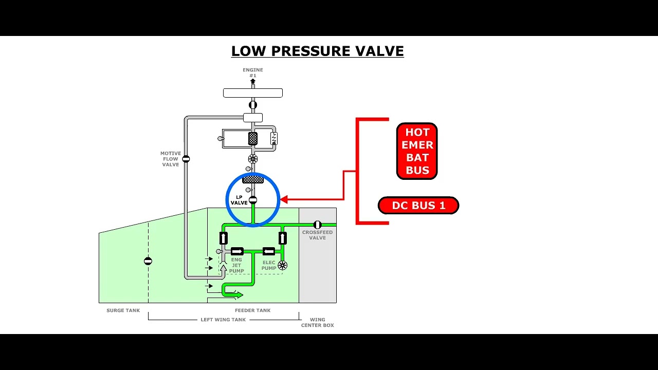
One LP shutoff valve is installed in each engine-feed line near the wing/pylon area. It isolates the associated engine from aircraft fuel supply when the engine is stopped or when emergency isolation is required.
2. Normal control
The engine master switch commands the related valve open for engine operation and closed for shutdown. A fire pushbutton overrides the normal master command and drives the valve closed.
3. Actuation and power
Each valve is operated by a dual-power-supply actuator with two motors, independent electrical sources and position switches. In emergency electrical configuration, the available essential path retains closure capability.
4. Indication and trapped fuel
Valve position is provided to fuel-system indication and maintenance functions. Thermal relief protects fuel trapped between closed valves from pressure rise caused by temperature.
5. Maintenance awareness
Do not confuse an electrical command, cockpit indication and mechanical valve position. Use approved tests and local visual provisions where required. Fire-isolation functionality is safety significant.
6. Position in the fuel path
The LP shutoff valve is the final aircraft fuel-system isolation valve before fuel enters the engine system. It is installed in each engine feed line near the wing/pylon interface.
Upstream are the tank pumps, gallery and crossfeed system. Downstream are engine-side fuel components controlled under the engine ATA chapters.
Closing the valve prevents continued aircraft fuel supply to a stopped or fire-affected engine.
7. Dual command sources
Engine master
The engine master switch controls normal opening and closing. Selecting the engine for operation commands the valve open. Selecting the engine off commands closure.
Fire pushbutton
The fire pushbutton commands closure independently of the normal engine-master demand. Fire isolation has priority.
The engine HP fuel valve also participates in engine shutdown. This means failure of the aircraft LP valve may not prevent the engine from stopping, but it reduces the ability to isolate the upstream fuel supply and is significant for fire protection.
8. Dual-power actuator
The valve actuator has two motors and position microswitches. Under normal power, both motors can operate together. The valve rotates through approximately a quarter turn between open and closed.
When the selected end position is reached, the microswitches remove motor power and report position.
Independent electrical sources support closure capability. In emergency electrical configuration, an essential supply path remains available to drive the valve closed.
9. Position indication
Position signals are used by the FUEL synoptic, alerts and maintenance system.
Possible states include:
- Commanded open and indicated open
- Commanded closed and indicated closed
- In transit
- Command/position disagreement
- Invalid or missing feedback
A position switch reports actuator-shaft state. It does not directly confirm internal sealing. A valve can reach the closed indication while leaking beyond the allowable limit.
10. Thermal relief
Fuel can be trapped between closed valves. Temperature rise causes expansion and pressure increase.
Thermal-relief features protect the closed section. Relief operation is usually hidden and does not mean the valve has failed.
11. Failure modes and consequences
Fails to close on engine-master command
The engine can shut down through engine-side control, but aircraft-side supply is not isolated as intended. The failure is normally evident through disagreement.
Fails to close on fire command
The failure may remain hidden until fire isolation is demanded. It becomes safety-significant when combined with an engine fire.
Fails to open
The engine lacks normal fuel supply. Start or continued operation is affected.
Position feedback fails
The actual valve can be correct while indication is lost. Dispatch capability can still be affected because the crew cannot confirm configuration.
Internal leakage
The valve indicates closed but does not fully isolate. Approved leak checks are required to confirm sealing performance.
12. Maintenance interfaces
Work around the LP valve affects:
- Fuel pipe connections
- Electrical power and actuator wiring
- Fire-control inputs
- Engine-master control
- Position feedback
- Pylon drainage and shroud systems
- Thermal-relief path
- Bonding and ignition prevention
Correct valve installation is both a fluid and electrical task.
13. Diagnostic model
For a position disagreement:
- Confirm the command source.
- Confirm power to both actuator channels.
- Determine whether the valve moved.
- Compare local position with cockpit feedback where approved.
- Inspect wiring and microswitch paths.
- Check mechanical obstruction or actuator coupling.
- Confirm sealing only through the applicable test.
Do not interpret a failed indication as automatic proof of a stuck valve.
14. Fire-isolation chain
Engine fire isolation involves several systems. The fire pushbutton can command:
- LP fuel shutoff
- Engine-side fuel shutoff through engine controls
- Hydraulic or pneumatic isolation
- Electrical generator isolation
- Fire-extinguishing readiness
ATA 28 contributes the aircraft-side fuel isolation. Failure of the LP valve does not mean every other fire action failed, but it leaves fuel available up to the engine-side shutoff and pylon line.
This is why fire-command closure is analyzed separately from normal engine-master closure.
15. Mechanical and electrical independence
The two actuator motors provide electrical redundancy, but they drive a common valve mechanism. A mechanical obstruction can defeat both motors.
Conversely, loss of one motor or power source can leave the other motor able to close the valve. Troubleshooting should identify whether the fault is common mechanical or channel-specific electrical.
16. Indication logic
The actuator microswitches change state near the valve end positions. During travel, the system can show an intermediate or disagreement condition.
Possible indication faults include:
- Open switch remains active after closure
- Closed switch does not activate
- Both signals invalid
- Wiring short or open
- Data-concentrator or display fault
The valve can be mechanically correct while the indication is wrong. The opposite is also possible if an actuator coupling is damaged.
17. Leakage and seat condition
A closed ball valve should reduce flow to the approved leakage level. Contamination, seat damage or incomplete travel can prevent full isolation.
A local closed indication cannot verify the seat. Approved leakage testing is needed when sealing performance is in question.
18. Maintenance safety
Before disconnecting the valve or adjacent pipe:
- The correct tank and gallery must be made safe.
- Trapped pressure must be considered.
- Fire and engine commands must be protected from inadvertent operation.
- Fuel spill and ignition controls must be established.
- Bonding and pipe-support configuration must be restored.
These are concepts only; the exact safe condition comes from current data.
Key takeaways
- The LP valve is the aircraft-side engine fuel isolation point.
- Fire control overrides normal engine-master logic.
- Dual power and position feedback support reliable isolation.
- Trapped-fuel thermal expansion remains a consideration after closure.
Approved-data boundary
This resource is a study aid. It must not be used to determine maintenance steps, limits, dispatch status, component removal criteria or aircraft configuration. Use the current applicable AMM, TSM/FIM, WDM, IPC, CMM, ALS/CDCCL data, operator procedures and task cards for real work.