Educational familiarization only. This original TechOpsBase resource explains system purpose and relationships. It does not reproduce Airbus pages, diagrams, task instructions or controlled maintenance data. Actual aircraft work requires current approved data, correct effectivity, operator procedures, authorization and supervision.
Learning objectives
- Explain the normal reason for closed crossfeed valves.
- Describe how two parallel valves provide interconnection redundancy.
- Recognize power and position-feedback considerations.
1. Normal configuration
With both crossfeed valves closed, the left and right engine-feed galleries remain independent. Each engine is supplied from its designated side.
2. Interconnection
Two valves are installed in parallel across the crossfeed pipe. Opening either suitable path can connect the galleries and allow one side or a centre-tank source to support both engines, depending on configuration and pressure.
The valves use single-power-supply actuators with position feedback and mechanical visual/deactivation features. Independent emergency DC supply supports availability in degraded electrical configuration.
3. Control
Manual pushbuttons provide direct control. Automatic emergency logic can command the required configuration. Maintenance analysis must distinguish command, electrical supply, actuator movement, valve position and actual pressure flow.
4. Failure reasoning
A failed closed valve may leave the second parallel valve available. A failed open valve can remove normal gallery independence. The operational and dispatch significance depends on the exact failure, additional faults and approved dispatch data.
5. Physical arrangement
The crossfeed system has two valves installed in parallel between the left and right engine-feed galleries. Each valve has its own actuator and control pushbutton.
With both valves closed, gallery independence is maintained. Opening either effective path connects the sides. Two valves provide redundancy for conditions where interconnection is important.
The valves are installed in the centre-tank region on the feed gallery. Their location means centre-tank pressure and APU-feed connections are part of the same fluid architecture.
6. Normal and alternate uses
Crossfeed can support:
- One side feeding both engines
- Centre-tank pressure being distributed to both sides
- APU supply from an alternate gallery
- Degraded electrical or pump configurations
- Ground pressure or maintenance configurations
Crossfeed is not a transfer function between storage tanks. It connects the engine-feed galleries. Tank quantity can change indirectly because both engines may draw from one source, but the crossfeed valve does not pump fuel between tanks.
7. Manual control
Each cockpit pushbutton commands its valve. An OPEN caption is based on actuator position feedback.
A green OPEN indication means the valve position switch reports open. It does not prove:
- The gallery has pressure
- Fuel is flowing
- The opposite source is available
- The valve ball is passing full flow without restriction
Pressure and tank-quantity trend provide additional evidence.
8. Emergency electrical configuration
The crossfeed valves remain important in emergency electrical configuration. Automatic logic can command them open so the remaining fuel source can support both engines.
If automatic opening fails, manual control can remain available depending on the electrical path. The dual-valve arrangement means one failed valve may leave another connection path.
9. Failure modes
Valve fails closed
The interconnection path is lost or reduced. Normal left/right independent feed can remain available.
Valve fails open
The galleries remain connected when independence is desired. A leak or pressure disturbance on one side can affect the other side.
Position indication fails
The valve can be correctly positioned while the cockpit shows a fault, or the indication can appear normal despite a mechanical problem. Local visual or approved functional confirmation may be required.
Both automatic commands fail in emergency configuration
Manual selection and gravity-feed operational strategies may preserve capability, subject to approved operating procedures.
10. Interfaces
Crossfeed interacts with:
- Wing and centre feed pumps
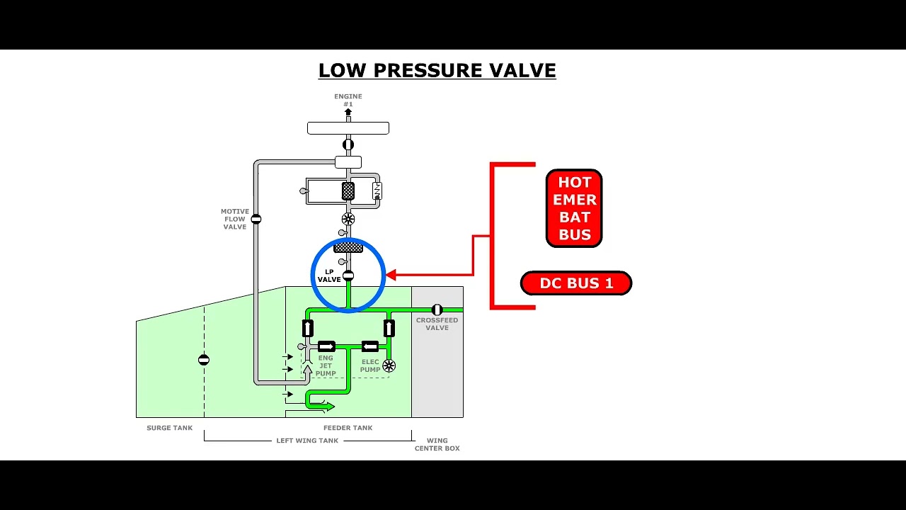
- Engine LP shutoff valves
- APU fuel feed
- Refuel/defuel pressure paths
- Wing transfer
- FQMS indication
- Electrical emergency configuration
A fault investigation must consider these interfaces.
11. Maintenance reasoning
When one engine appears to be supplied from the wrong tank:
- Check crossfeed selection and indicated position.
- Check which pumps are producing higher pressure.
- Compare left and right tank quantity trends.
- Review LP-valve status.
- Review centre-tank pump operation.
- Consider a leaking check valve or crossfeed valve.
- Use approved pressure and valve tests.
Quantity trend can reveal actual fuel sourcing when valve indication alone cannot.
12. Actuator and power considerations
Each crossfeed valve uses a single-motor actuator with position switches. The two valves are supplied through separate electrical paths so the interconnection function is not dependent on one actuator.
Emergency configuration availability is a deliberate design feature. When normal electrical distribution is reduced, the remaining fuel architecture must still be able to connect available sources to both engines.
A maintenance investigation should distinguish:
- Pushbutton command
- Electrical power reaching the actuator
- Actuator movement
- Valve-shaft position
- Position-switch feedback
- Actual gallery pressure equalization
A failure at one layer can imitate a failure at another.
13. Pressure masking
With crossfeed open, pressure from a healthy source can reach both sides. This can hide a failed local pump or pressure source.
For example, a left pump can be unavailable while right-side pressure keeps the left gallery pressure switch satisfied. To prove the local source, the approved test may require a configuration that prevents pressure from the opposite side.
This is a general troubleshooting principle: interconnection improves operation but can reduce fault visibility.
14. Fuel-balance effect
Crossfeed does not directly transfer fuel between tanks, but it changes which tanks the engines consume from.
If both engines are supplied primarily from one wing, that wing quantity decreases faster and lateral imbalance develops. FQMS quantity and imbalance monitoring therefore provide indirect evidence of actual source selection.
A valve that leaks open can cause an unexpected consumption pattern even when the cockpit command is closed.
15. Local maintenance features
Crossfeed valves can include local visual position and deactivation provisions. These support maintenance and approved dispatch configurations.
Local position must be interpreted carefully. A marked actuator position can confirm shaft orientation but not valve sealing or unrestricted flow. Functional or leakage tests may still be required.
16. Scenario reasoning
Both engines consume from one side
Check centre-pump status, crossfeed position, local pump pressure and tank quantity trends.
Crossfeed fault after selection
Separate command failure, power failure, actuator failure, mechanical blockage and position-switch failure.
Crossfeed remains indicated open
Confirm whether the valve is mechanically open or the feedback circuit is stuck. Check the second parallel valve separately.
Pressure exists with all local pumps off
Look for crossfeed pressure, centre-tank pressure, APU-feed interaction or check-valve leakage before concluding that a pump is running unexpectedly.
Key takeaways
- Crossfeed is normally closed to preserve left/right independence.
- Two valves provide a redundant interconnection path.
- Valve position feedback does not directly prove fuel flow.
- Emergency electrical availability is part of the design.
Approved-data boundary
This resource is a study aid. It must not be used to determine maintenance steps, limits, dispatch status, component removal criteria or aircraft configuration. Use the current applicable AMM, TSM/FIM, WDM, IPC, CMM, ALS/CDCCL data, operator procedures and task cards for real work.