Educational familiarization only. This original TechOpsBase resource explains system purpose and relationships. It does not reproduce Airbus pages, diagrams, task instructions or controlled maintenance data. Actual aircraft work requires current approved data, correct effectivity, operator procedures, authorization and supervision.
Learning objectives
- Trace the normal APU fuel-feed path.
- Explain when the dedicated APU pump operates.
- Describe automatic line-damage isolation.
1. Fuel sources
The APU feed connects to the engine-feed gallery. When gallery pressure is adequate, engine-feed pumps can supply the APU. If inlet pressure is insufficient, the dedicated 28 V DC APU fuel pump provides pressure, including battery-start capability.
2. Valves and line protection
The feed path includes an APU isolation valve and an APU low-pressure valve. A shrouded line runs toward the APU. Adjacent damage-detection conductors monitor line integrity; detected damage commands pump shutdown and valve closure.

The pipe shroud drains toward an external mast so leakage evidence can be detected without allowing fuel to accumulate in the fuselage.
3. Control inputs
APU master and fuel-demand logic interact with:
- Feed-gallery pressure
- Emergency shutdown and fire commands
- Line-damage detection
- Valve position and pump status
4. Thermal relief and drain functions
Trapped fuel can expand after shutdown. Thermal-relief paths protect the closed section. Vent/drain provisions support controlled maintenance and line servicing.
5. Maintenance awareness
A pump-off or valve-closed indication does not by itself prove that the line is depressurized or free of trapped fuel. Line-damage and isolation tests are safety functions and must be performed exactly as specified.
6. APU fuel-source hierarchy
The APU can receive fuel from several available pressure sources.
When the engine-feed gallery is pressurized, fuel can reach the APU line from the normal feed architecture. Depending on tank state, gallery pressure may come from a centre-tank pump, a wing main pump, a wing standby pump or the opposite side through crossfeed.
If gallery pressure is inadequate, the dedicated APU electric pump provides local pressure. This supports APU start and operation during ground or battery-related configurations.
The source changes automatically according to pressure and command logic. The APU does not need a manual source selector for each pump.
7. Dedicated APU pump and canister
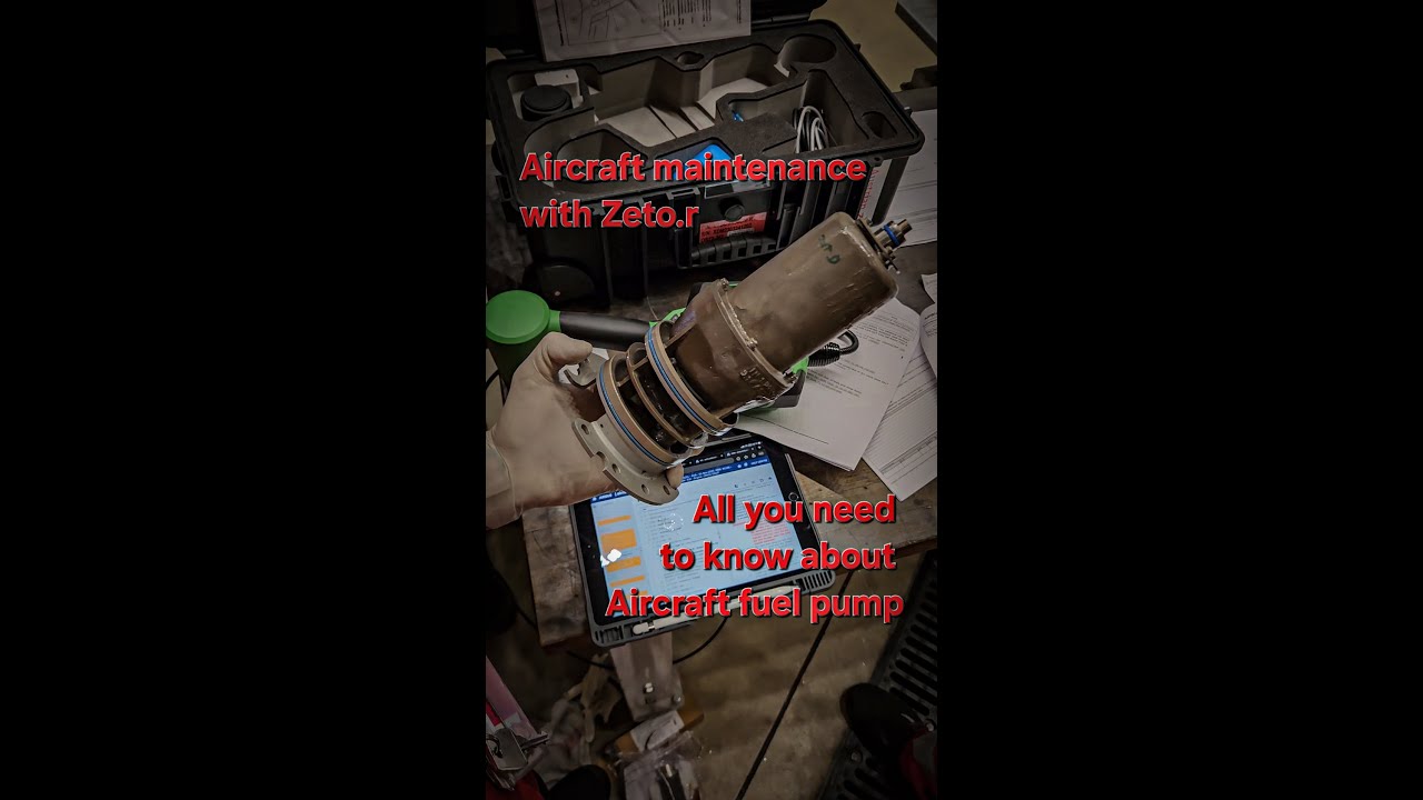
The APU pump is an electric pump installed in a canister. The canister supports installation, fuel containment and controlled pump-element removal.
The pump is commanded when APU fuel demand exists and engine-feed gallery pressure is not sufficient. A pressure switch provides feedback.
Pump status depends on:
- APU master or start demand
- Available electrical power
- Gallery pressure
- Pump command
- Pressure-switch state
- Isolation-valve configuration
- Fire or emergency shutdown input
8. APU LP valve
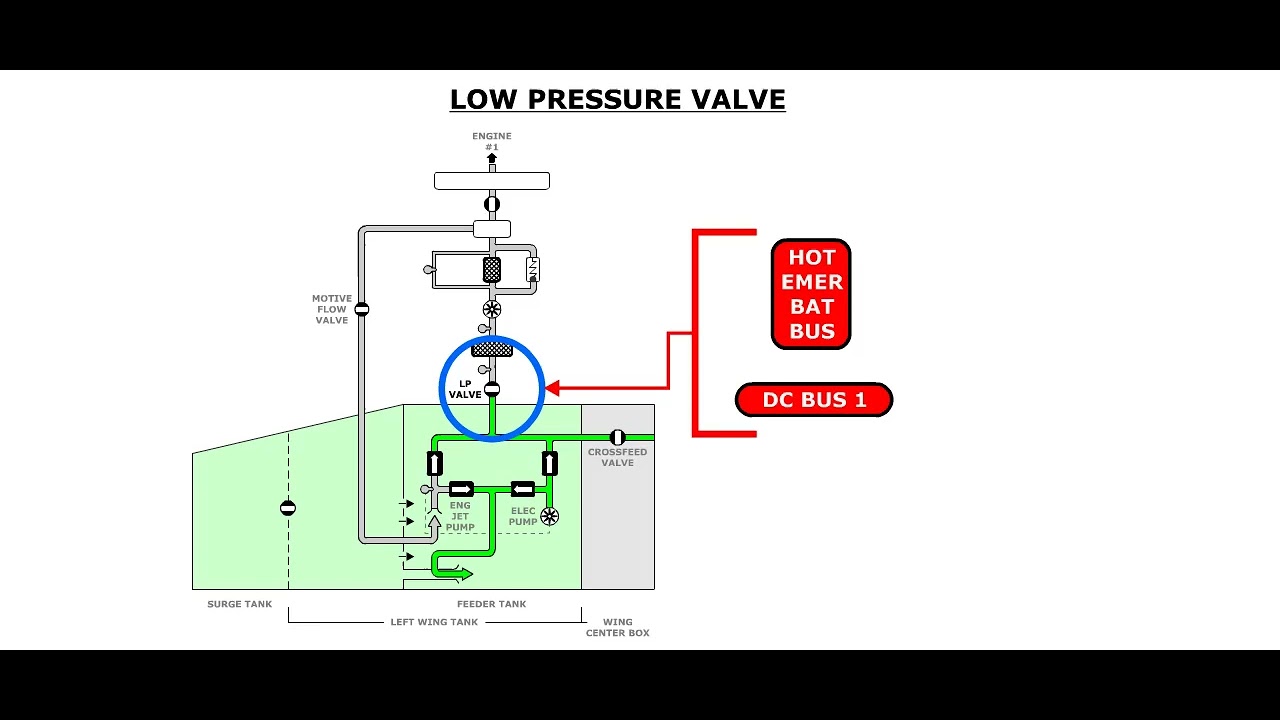
The APU LP valve is part of the fuel path toward the APU. It provides normal opening and closing control and can contain thermal-relief elements.
Valve position is monitored. A commanded-position disagreement can produce an APU feed fault.
The valve and isolation valve have different functions. One controls the normal APU feed path; the other isolates a damaged section or responds to specific protection logic.
9. APU isolation valve
The isolation valve closes to limit fuel release after a line-damage condition. It is positioned so a long section of APU feed pipe can be isolated from upstream fuel pressure.
Automatic isolation can be initiated by:
- Detected line breakage
- Defined decompression or structural-damage logic
- APU fire or emergency shutdown
- Other configuration-dependent protection commands
The exact logic differs with modification status and must be checked against effectivity.
10. Line-break detection
Later configurations add switches or detection features along the APU feed-line installation. The purpose is to detect structural separation or pipe damage that could release fuel.
A detected condition can:
- Stop the APU pump
- Close isolation and LP valves
- Generate a cockpit alert
- Command APU shutdown or deselection guidance
The detection chain includes the physical switch, wiring, control logic, valve actuation and feedback. A fault in any part can produce a false alert or loss of protection.
11. Rapid decompression and damage considerations
The APU line crosses aircraft zones where structural damage or rapid decompression could affect the pipe. Protection logic considers events that can compromise the line even without a direct fuel-pressure sensor detecting the break.
This illustrates system integration: an airframe or pressure event can command an ATA 28 isolation action.
12. Thermal pressure relief
Fuel trapped between closed valves expands when temperature rises. Thermal-relief paths prevent excessive line pressure.
The APU line uses more than one relief path or element so a single failure does not remove all protection. Relief can return fuel toward the line or tank depending on valve arrangement.
There is normally no cockpit indication that a relief valve has opened. Relief function is a hidden protection.
13. Pipe shroud and drain
The APU feed pipe is enclosed by a secondary shroud over vulnerable sections. Leakage is routed to an external drain mast.
The shroud protects occupied or equipment areas from free fuel. The drain outlet gives maintenance a visible clue. A blocked drain can remain hidden until a primary line leak occurs.
14. APU vent and drain function
Vent and drain provisions support safe pressure equalization and removal of residual fuel during approved maintenance. They do not mean the line is automatically empty when the pump stops.
Trapped fuel and pressure must be managed through the applicable task.
15. Operation and automatic test
Before flight or during defined power-up conditions, the system can perform tests of standby supply and isolation logic.
An automatic test can verify:
- Pump availability
- Pressure-switch response
- Valve movement
- Line-detection switch path
- Control relays or logic
- Cockpit indication
A failed test can reduce dispatch capability even though the APU still operates through another source.
16. Cockpit indication
The FUEL synoptic presents APU feed status. Alerts can distinguish:
- Feed path incorrectly closed
- Possible APU line fracture
- Pump or valve fault
- Command/position disagreement
The message identifies a system condition, not necessarily the failed component.
17. Redundancy examples
- Loss of normal gallery supply can be covered by the APU pump.
- Loss of one wing pump can be covered by standby or other gallery sources.
- Crossfeed can provide an alternate side.
- One thermal-relief path can cover another.
- Shroud drainage limits leakage consequence.
- Automatic isolation limits fuel release after damage.
The combined architecture supports continued APU supply while preserving rapid isolation capability.
18. Troubleshooting model
For an APU feed fault:
- Identify whether the issue is supply loss or unwanted isolation.
- Confirm which fuel source should be active.
- Check gallery pressure and APU pump command.
- Check LP and isolation valve command/position.
- Review line-break or decompression inputs.
- Review electrical power and relay/control status.
- Check shroud drain evidence.
- Follow current fault-isolation data.
Do not assume the dedicated APU pump is the cause merely because the APU lacks fuel pressure.
Key takeaways
- The APU normally uses gallery pressure when available.
- The dedicated pump supports low-pressure and battery-start conditions.
- Automatic isolation limits consequences of feed-line damage.
- Shroud drainage and thermal relief are separate protection functions.
Approved-data boundary
This resource is a study aid. It must not be used to determine maintenance steps, limits, dispatch status, component removal criteria or aircraft configuration. Use the current applicable AMM, TSM/FIM, WDM, IPC, CMM, ALS/CDCCL data, operator procedures and task cards for real work.