Educational familiarization only. This original TechOpsBase resource explains system purpose and relationships. It does not reproduce Airbus pages, diagrams, task instructions or controlled maintenance data. Actual aircraft work requires current approved data, correct effectivity, operator procedures, authorization and supervision.
Learning objectives
- Distinguish centre, wing-main and wing-standby pump roles.
- Explain pressure-based source priority.
- Describe automatic standby testing and centre-tank scavenge.
1. Engine-feed architecture
The left and right engine-feed galleries normally support their associated engines. Crossfeed valves can join the sides when required. Fuel sources include centre-tank pumps and wing-tank main/standby pumps.

2. Centre-tank pumps
Centre-tank pump delivery pressure is higher than wing-pump pressure, so centre fuel normally takes priority when the centre pumps are operating. Control is mainly automatic through the FQMS with manual override capability.
During selected critical flight phases, automatic logic can stop centre-tank pumps. The exact control condition and effectivity must be confirmed from current data.
3. Wing pumps
Each wing feed system includes main and standby pump capability. Main pumps are normally manually selected. Standby pumps can support the feed when the main source is unavailable and are automatically operated briefly during preflight/taxi testing to prove pump, pressure switch and control operation and help remove collected water.
4. Protection and monitoring
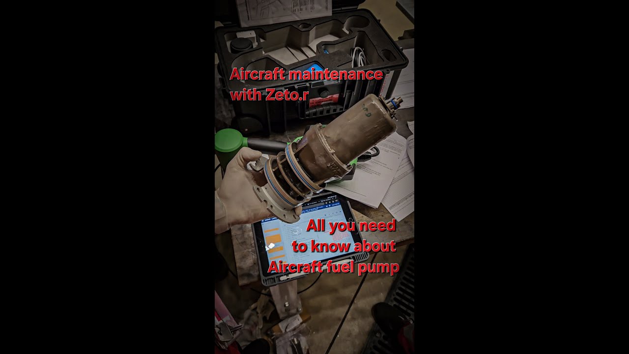
Pump circuits include electrical protection, pressure sensing and status feedback. Centre pumps use regulated fixed-frequency supply units with ground-fault detection. Pump elements are installed in canisters that support controlled removal and drainage.
5. Centre-tank fuel scavenge
Jet pumps collect residual centre-tank fuel from low areas and return it toward wing tanks. Motive flow comes from wing-feed pumps, and the FQMS controls the scavenge cycle.
6. Left and right feed-system independence
The aircraft has left and right engine-feed galleries. With crossfeed valves closed, each gallery supplies its associated engine from the corresponding wing tank or from centre-tank sources connected to the system.
Independence limits the effect of a leak or pump failure on one side. Crossfeed provides controlled interconnection when needed.
7. Wing-tank pump arrangement
Each wing collector box contains main and standby pump capability. The pumps are immersed electric pumps installed in canisters.
The canister arrangement allows the pump element to be removed while managing residual fuel and maintaining the surrounding tank installation. Check valves help prevent reverse flow and preserve gallery pressure.
The main pump is the normal wing source. The standby pump is available when the main source is lost and is tested automatically to verify availability.
8. Centre-tank pump arrangement
The centre tank has left and right pumps. Their delivery pressure is higher than the wing-pump pressure. When operating, they therefore feed the engine galleries in preference to the wing pumps.
Each centre pump is powered through a Fixed Frequency Supply Unit. The FFSU provides controlled electrical supply and ground-fault interruption. A detected leakage current can disconnect the pump to reduce ignition risk.
The pump element is installed in a canister with a drain provision. Canister and pump work remains controlled by approved fuel-safety tasks.
9. Pressure hierarchy
Fuel follows the source with adequate higher pressure. This creates an automatic priority without a separate selector valve for every source.
Typical relationships are:
- Centre pumps operating: centre fuel takes priority.
- Centre pumps stopped or centre empty: wing pumps supply.
- One centre pump operating with crossfeed available: one pump may support both engines within design capability.
- Wing main pressure lost: standby pump can preserve the local feed.
- All electric pressure lost: gravity-feed capability may exist within operating limitations.
Pressure hierarchy explains why pump selection and actual source are not always the same. A selected wing pump can be running while centre pressure prevents it from contributing significant flow.
10. Centre-pump automatic control
FQMS logic controls centre pumps using tank state and flight configuration. The pumps operate when selected, centre fuel is available and no inhibit applies.
During takeoff and selected landing conditions, the pumps are stopped to avoid supplying potentially contaminated centre-tank low-point fuel during a critical phase. Slat/flap configuration provides part of the flight-phase input.
After the inhibit clears and valid conditions return, the system can resume centre feed.
11. Wing standby-pump automatic test
Before flight, the system can run standby pumps for a short automatic test. The purpose is to verify:
- Electrical supply
- Pump motor operation
- Pressure generation
- Pressure-switch response
- Control and indication
The test also provides motive flow for collector-box water-scavenge jet pumps. This links pump availability testing with water management.
12. Engine-feed gallery and pressure sensing
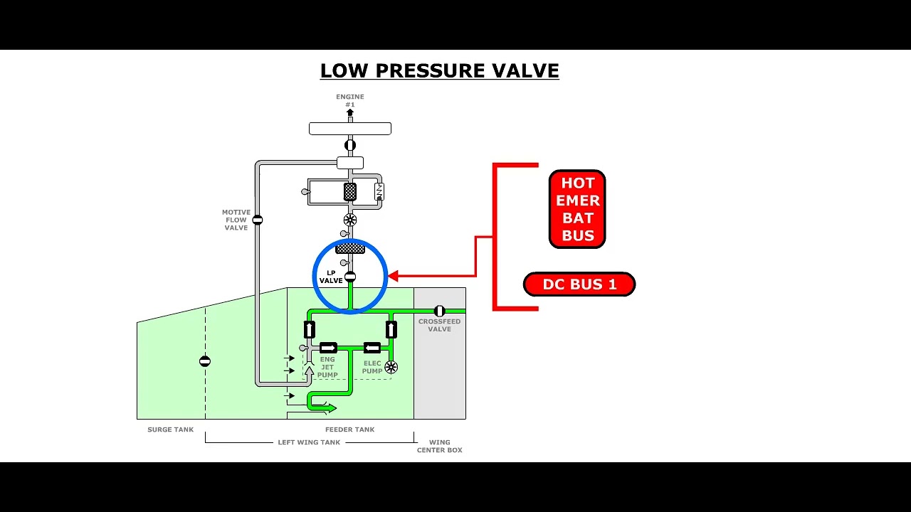
The gallery carries fuel from the tank pumps toward the crossfeed and engine LP valve. Pressure switches or sensors provide evidence of source performance.
A low-pressure indication can result from:
- Pump not commanded
- Electrical supply unavailable
- Pump internal failure
- Inlet starvation
- Check-valve or gallery leak
- Pressure-switch failure
- Wiring or data fault
- Another source dominating the gallery in a way that changes expected feedback
The approved troubleshooting path separates these causes.
13. Crossfeed interaction
Opening crossfeed joins the two sides. This can allow one tank or centre pump to support both engines. It can also make fault isolation more complex because pressure from the healthy side can mask loss of the failed-side pump.
For maintenance checks, gallery configuration must be known. A healthy pressure indication with crossfeed open does not prove the local source is operating.
14. Centre-tank scavenge after depletion
Low residual fuel can remain in centre-tank structural areas after the main centre pumps can no longer provide normal feed.
Jet pumps use motive flow from wing-feed sources to move residual centre fuel toward usable areas. FQMS logic controls the scavenge period.
Scavenge reduces unusable fuel but does not mean the centre tank is physically dry. Quantity indication and maintenance drainage remain separate.
15. Gravity feed
If electric pump pressure is unavailable, fuel can reach an engine through gravity under defined altitude, attitude and fuel-level conditions.
Gravity-feed capability depends on:
- Fuel head
- Aircraft altitude
- Gallery and valve configuration
- Engine demand
- Tank venting
- Line condition
It is an operational fallback, not proof that a pump fault has no maintenance significance.
16. Failure-awareness map
Main pump fails
Standby pump can preserve supply. The failure is normally indicated by pressure and control logic.
Standby pump unavailable
Normal operation can continue on the main pump, but redundancy is reduced.
Centre pump fails
The other centre pump or wing pumps can supply, depending on configuration. Centre fuel use and dispatch capability may be affected.
Ground fault detected
The FFSU removes power to the affected centre pump. The fault concerns both pump availability and ignition protection.
Pressure-switch fault
Pump operation and indication can disagree. Independent pressure or quantity trend becomes important.
Check valve leaks
Reverse flow or loss of retained pressure can occur without a direct component-position indication.
17. Maintenance reasoning sequence
For a feed-pump fault:
- Confirm expected source and flight/ground configuration.
- Confirm pump selection and FQMS command.
- Confirm electrical supply and protection status.
- Confirm pump pressure feedback.
- Check crossfeed configuration and masking pressure.
- Review tank quantity and collector-box availability.
- Review maintenance messages.
- Follow approved isolation and safety procedures.
Pump replacement should be the result of evidence, not the first response to a low-pressure message.
Key takeaways
- Pressure hierarchy determines which available source supplies the engines.
- Standby pumps are active protection, not unused spares.
- Pump indication depends on command, electrical supply, pressure and feedback.
- Centre-tank fuel scavenge reduces unusable fuel after normal depletion.
Approved-data boundary
This resource is a study aid. It must not be used to determine maintenance steps, limits, dispatch status, component removal criteria or aircraft configuration. Use the current applicable AMM, TSM/FIM, WDM, IPC, CMM, ALS/CDCCL data, operator procedures and task cards for real work.