Educational familiarization only. This original TechOpsBase resource explains system purpose and relationships. It does not reproduce Airbus pages, diagrams, task instructions or controlled maintenance data. Actual aircraft work requires current approved data, correct effectivity, operator procedures, authorization and supervision.
Learning objectives
- Identify major ignition-prevention design layers.
- Explain ground-fault and bonding roles.
- Recognize why in-tank wiring and equipment need controlled configuration.
1. Layered protection
Ignition prevention covers the tank structure, wiring, pumps, valves, probes, connectors, heat exchangers, adjacent systems and external fuel lines. No single device provides all protection.
2. Electrical energy control
Fuel-quantity circuits are designed to keep energy in the tank below unsafe levels. Protection depends on wiring separation, shielding, connector integrity, probe condition and correct grounding.
Pump systems add ground-fault monitoring or interruption. Centre-tank pumps are supplied through fixed-frequency units that regulate motor power and detect downstream ground faults. Wing and APU pump circuits use their own protective arrangements.
3. Bonding and lightning
Bonding gives lightning and static current a low-resistance controlled path. Poor contact, corrosion, wrong fasteners, damaged braid or incorrect surface preparation can defeat the intended path even when the component appears installed.
4. Mechanical and thermal sources
Foreign objects can contact pump impellers and create friction sparks. Hot-air duct leakage or another adjacent heat source can raise tank-surface temperature. Fuel leaks near electrical or hot equipment create another ignition route.
5. Maintenance controls
- Protect tank cleanliness.
- Restore bonds exactly as specified.
- Maintain wiring separation and clamping.
- Use correct connector, sealant and material.
- Investigate pump, FFSU/GFI or wiring faults through approved data.
- Treat CDCCL references as mandatory configuration controls.
6. Ignition-prevention architecture
The A350 ignition-prevention design covers the tank interior, tank structure, wiring, fuel equipment, adjacent zones and external fuel pipes.
The functions are redundant. Loss of one bonding path, one overheat-detection loop or one protective feature may not create an immediate hazard because another layer remains. This is useful for safety but makes many failures hidden.
7. Structural lightning protection
Lightning current must pass through the aircraft without producing an arc or hot spot capable of igniting fuel vapour.
Protection includes:
- Conductive structural paths
- Bonded joints
- Controlled fasteners
- Metallic or conductive features in composite structure
- Spark containment at penetrations
- Shielding and separation
- Surface protection around tank boundaries
A structural repair near a fuel tank must preserve both mechanical strength and electrical behavior. Conductivity, joint resistance and current path are part of the approved design.
8. Equipment and pipe bonding
Fuel pipes, valves, pumps and other conductive equipment are bonded to structure. Bonding reduces electrical potential difference and carries unwanted current away.
Some components have dual bonding. One degraded bond may not be evident or immediately hazardous. The maintenance task exists to reveal the hidden reduction in redundancy.
Bonding quality depends on:
- Correct bonding hardware
- Clean and prepared contact surfaces
- Corrosion protection
- Correct assembly
- Measured resistance where required
- Protection from later disturbance
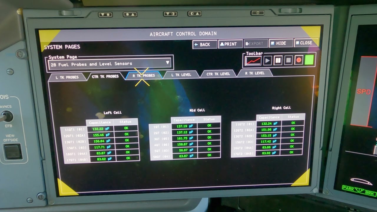
9. FQMS and sensor wiring
Quantity probes and related sensors are designed as low-energy circuits. Their safety depends on limiting the energy that could enter the tank.
Wiring safeguards include:
- Physical separation from higher-power circuits
- Shielding and grounding
- Controlled connector configuration
- Protection at tank penetrations
- Approved repair methods
- Data-concentrator isolation
A short circuit between a high-energy circuit and an intrinsically safe probe circuit is one of the conditions the design must prevent. Routing and separation are therefore CDCCL-sensitive.
10. Engine-feed and centre-pump electrical protection
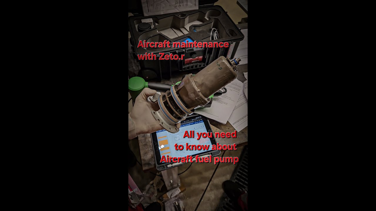
Electric fuel pumps are potential ignition sources if electrical or mechanical faults are uncontrolled.
Protection can include:
- Ground-fault interruption
- Fixed-frequency controlled supply
- Automatic shutdown for leakage current
- Pressure and status monitoring
- Pump-canister containment
- Approved internal materials and clearances
- Cooling and lubrication by fuel
- Dry-run limitations
The Fixed Frequency Supply Unit for a centre-tank pump includes a ground-fault detection function. A manual test/reset facility supports maintenance confirmation. The exact test method remains approved data.
11. Friction and foreign-object risk
A metallic object contacting rotating pump parts can create frictional heating or sparks. Tank cleanliness and foreign-object control are therefore ignition-prevention measures.
After tank work:
- Account for tools and consumables.
- Remove wire clippings, fastener fragments and abrasive material.
- Protect open pump and pipe interfaces.
- Use approved cleaning methods.
- Complete required inspection before closure.
Foreign-object control is not only about preventing blockage.
12. Pressure switches, probes and in-tank connectors
Small electrical components can still matter because they are located in or near fuel vapour.
Pressure switches provide pump or gallery status. FQI probes and point-level sensors support quantity and high-level protection. In-line fuel-properties units measure fuel characteristics during refuel.
The equipment is designed with limited energy, sealing, insulation and approved interfaces. Using an incorrect component or repair can alter those characteristics.
13. Fuel leakage protection
The ignition-prevention strategy also keeps fuel away from possible ignition sources.
Examples include:
- Pipe shrouds around selected feed lines
- Dedicated drain masts
- Ventilated leading- and trailing-edge zones
- Sealed or explosion-resistant electrical equipment
- Controlled fuel-pipe routing
- Fuel-leak detection and isolation logic
- Drainage around the APU feed line
A blocked drain, damaged shroud or unsealed connector can reduce this protection without creating an immediate cockpit message.
14. Adjacent electrical sources
Equipment outside the tank can still ignite leaked fuel. Electrical boxes, connectors, wiring and motors near the wing or centre-tank boundary are selected and installed to control arcs and hot surfaces.
Ventilation and drainage reduce accumulation. Electrical connector configuration and enclosure condition preserve explosion resistance.
Maintenance should consider the complete zone. Replacing a fuel component while leaving damaged nearby electrical wiring unresolved does not restore the safety barrier.
15. Adjacent heat sources
Hot-air ducts, APU or engine zones and electrical equipment can heat tank structure or leaked fuel.
Protection includes:
- Separation and insulation
- Overheat-detection loops
- Fire-resistant structure
- Controlled duct routing
- Shutoff logic
- Inspection of clamps and clearances
A single failed overheat loop may leave the second loop available, but the reduction in redundancy can affect dispatch and requires rectification under approved data.
16. Inerting and oxygen reduction
The inerting system can reduce oxygen concentration in the ullage, lowering flammability. It works alongside ignition-source prevention.
Inerting does not remove the need to maintain bonds, wiring separation, pump protection or drainage. The aircraft must remain safe during phases or conditions where inerting performance is reduced or unavailable.
17. Hidden versus evident failures
Often hidden
- Bond degradation
- Shield or separation error
- Blocked drain
- One failed redundant lightning path
- Internal pump wear before a monitored limit
- Incorrect material or fastener configuration
More likely evident
- Pump fault with pressure loss
- Valve-position disagreement
- Detected ground fault
- Overheat-loop alert
- APU line-break alert
- Fuel overflow indication
This distinction helps explain why maintenance tasks exist even when the system has no reported operational fault.
18. Maintenance actions with high ignition-prevention sensitivity
- Fuel-pump removal or replacement
- FQI probe or harness work
- Structural repair near tank boundaries
- Bonding-jumper work
- Wiring repair or rerouting
- Tank access-panel installation
- Pipe or valve installation
- Connector replacement
- Sealant and coating repair
- Work around heat or bleed-air sources
Each action can affect more than one protection layer.
19. Diagnostic discipline
When investigating an ignition-prevention message or maintenance finding:
- Identify whether the condition is detected or hidden.
- Identify the remaining redundant protection.
- Identify the associated CDCCL or airworthiness limitation.
- Separate component function from installation configuration.
- Check adjacent systems and zones.
- Use approved measurements and inspections.
- Record restoration of the controlled feature.
The objective is not merely to clear the message. It is to restore the complete safety architecture.
Key takeaways
- Ignition prevention combines electrical, structural, mechanical and thermal barriers.
- Ground-fault protection does not eliminate the need for wiring and connector integrity.
- Bonding quality must often be measured, not assumed.
- Foreign-object control is a fuel-tank safety task.
Approved-data boundary
This resource is a study aid. It must not be used to determine maintenance steps, limits, dispatch status, component removal criteria or aircraft configuration. Use the current applicable AMM, TSM/FIM, WDM, IPC, CMM, ALS/CDCCL data, operator procedures and task cards for real work.