Educational familiarization only. This original TechOpsBase resource explains system purpose and relationships. It does not reproduce Airbus pages, diagrams, task instructions or controlled maintenance data. Actual aircraft work requires current approved data, correct effectivity, operator procedures, authorization and supervision.
Learning objectives
- Explain why water accumulates in aircraft fuel tanks.
- Describe the role of water-scavenge jet pumps.
- Distinguish automatic scavenge from manual drainage.
1. Why water matters
Water enters the system through fuel uplift and condensation. Excess water can contribute to:
- Icing and restriction
- Microbiological contamination
- Corrosion or material degradation
- Incorrect quantity indication
- Reduced fuel quality
2. Scavenge arrangement
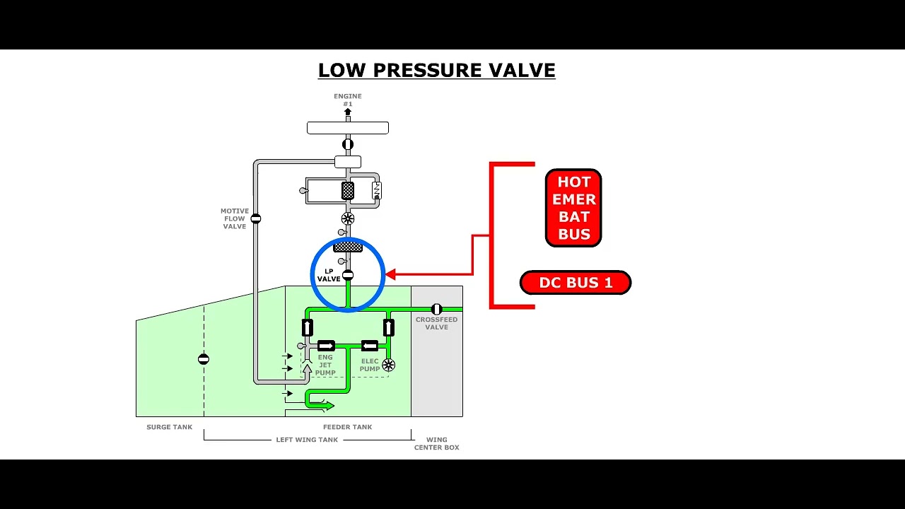
Jet pumps are installed at low points in the wing collector boxes and centre tank. Motive flow from fuel-feed pumps draws a water/fuel mixture from low areas and discharges it near engine-feed pump pickup areas, where the small concentration is carried through the normal fuel flow.

Clack valves and drain holes allow water from wing-tank and centre-tank areas to migrate toward scavenge pickup locations.
3. Manual drainage
Manual water-drain valves remain necessary for ground maintenance. Different tank locations use direct, remote-direct or indirect drain arrangements. The correct method depends on fuel quantity, aircraft attitude, temperature and the approved task.
4. Troubleshooting awareness
Evidence of excessive water can point to operating environment, uplift quality, failed scavenge motive flow, blocked pickup, stuck valve or incorrect drain practice. One sample is not automatically representative of the entire tank.
6. How water enters the tanks
Water cannot be completely prevented from entering aircraft fuel tanks.
Moist air enters through the vent system as ambient pressure rises during descent. When this air contacts cold tank surfaces, moisture can condense and freeze. The ice later melts when the structure warms.
Fuel also contains a small quantity of dissolved water. Cold fuel holds less water in solution, so temperature reduction can cause free water to separate. Refueling can also introduce small amounts of suspended water.
Because water is denser than fuel, it settles toward structural low points.
7. Why water matters
Excess water can:
- Freeze and restrict small passages or pump inlet screens
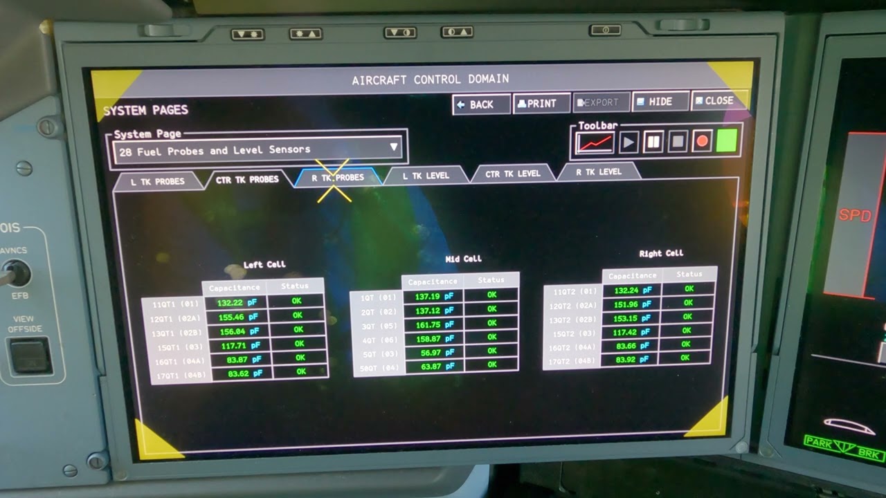
- Cause inaccurate capacitance-based quantity measurement
- Promote microbiological growth
- Contribute to corrosion or coating deterioration
- Reach an engine in a concentration greater than intended
- Accumulate behind ribs and stringers
- Mask or complicate fuel contamination
Water control is therefore a fuel-quality, engine-reliability and tank-maintenance issue.
8. Wing collector-box scavenge
Each wing collector box has a jet pump located near a low point. Motive flow comes from the associated wing engine-feed pump through a check valve.
The jet pump uses high-velocity motive fuel to create suction at its pickup. It draws a water-fuel mixture from the local low point and discharges the diluted mixture close to the feed-pump pickup area.
Pickup and discharge location matter. If the pickup is not located where water gathers during the intended aircraft attitude, scavenge effectiveness is reduced. If discharge creates excessive mixing, the water can be spread instead of collected. Design changes can therefore reposition pickups and add dilution openings.
9. Centre-tank scavenge
The centre tank has multiple jet-pump pickups around the left and right sides of rib 1. Drain holes let water migrate from outboard structural areas toward inboard low points.
Motive flow is supplied by the associated centre-tank engine-feed pumps. The pickups are positioned for the attitude where water is expected to collect and where engine fuel flow can accept a controlled diluted concentration.
The system is designed to move water, not to deliver a slug of nearly pure water to the engine. Dilution with fuel is part of the protection.
10. Scavenge depends on pump operation
A jet pump has no electric motor. It works only when motive flow is present. Loss of the associated feed-pump pressure can therefore reduce water-scavenge capability even though no dedicated scavenge fault is indicated.
This relationship is useful during troubleshooting. A water-accumulation problem may be connected to pump operation, motive-flow check valves, pickup position or blockage.
11. Ground water drainage
Manual low-point drains provide another method of water removal. Wing collector boxes use indirect drain paths. Centre and surge-tank areas use direct or remotely operated drains depending on accessibility.
Ground drainage effectiveness depends on:
- Aircraft attitude
- Fuel quantity
- Time allowed for water to settle
- Fuel and structure temperature
- Whether ice has melted
- Condition of the drain path
- Correct sampling technique
A clean first sample does not always prove the entire tank is free of water.
12. Climate and operating pattern
Aircraft operating in hot, humid climates can experience frequent moisture entry and microbiological activity. Aircraft cycling between cold cruise conditions and warm ground conditions can create significant condensation.
Long ground time, low utilization and repeated partial refueling can also affect water behavior. Maintenance programs use operating experience and approved intervals to manage this risk.
13. Quantity-indication relationship
Free water around a capacitance probe changes the local dielectric environment. The quantity system may interpret the condition differently from normal fuel. Water can therefore contribute to unstable or inaccurate readings.
Quantity faults should not automatically be treated as electrical failures. Fuel condition, water, contamination and temperature can be part of the evidence.
14. Microbiological contamination
Microorganisms live at the fuel-water interface. Growth can produce sludge, acidic by-products and blockage. Water removal is therefore one of the controls against microbiological contamination.
Scavenge and draining do not replace approved contamination treatment. They reduce the environment that supports growth.
15. Failure-awareness map
Jet-pump pickup blocked
Water remains at the low point. There may be no direct indication.
Motive flow unavailable
The jet pump stops scavenging even if the pickup is clear.
Drain holes blocked
Water remains trapped behind a structural barrier.
Manual drain valve leaks or does not open
Fuel containment or maintenance drainage is affected.
Discharge location disturbed
The mixture may not enter the intended feed region or may create excessive local water concentration.
16. Maintenance reasoning
When water is repeatedly found:
- Confirm the aircraft has had time and temperature conditions for water to settle and ice to melt.
- Consider vent-air moisture and uplifted fuel quality.
- Review whether the associated feed pumps have been operating normally.
- Consider jet-pump motive flow and pickup condition.
- Review drain-path configuration and structural repairs.
- Check for microbiological evidence.
- Use current approved inspection and sampling data.
The objective is to identify why water remains, not only to remove one sample.
Key takeaways
- Water scavenge reduces accumulation during operation.
- Manual drainage verifies and removes water at controlled low points.
- The engine-feed pumps provide motive flow for several scavenge functions.
- Fuel sampling and drainage must follow the current approved method.
Approved-data boundary
This resource is a study aid. It must not be used to determine maintenance steps, limits, dispatch status, component removal criteria or aircraft configuration. Use the current applicable AMM, TSM/FIM, WDM, IPC, CMM, ALS/CDCCL data, operator procedures and task cards for real work.