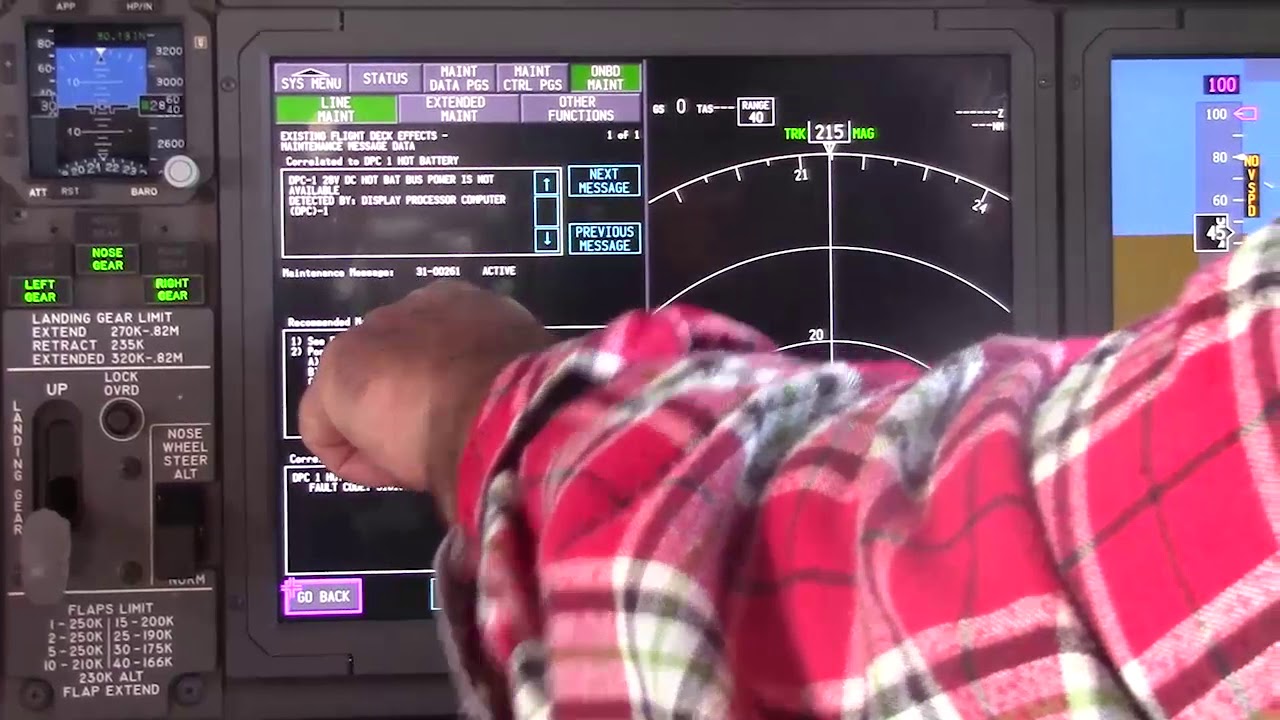
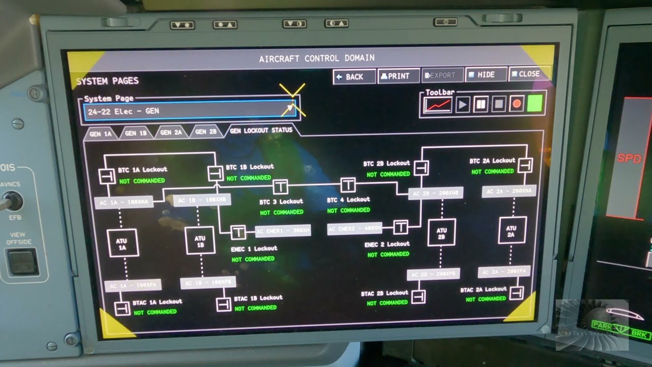
Educational familiarization only. This TechOpsBase resource is an original learning transformation grounded in a privately supplied B737 MAX ATA 24 source. It does not reproduce manufacturer task steps, limits, figures or controlled maintenance instructions. Current approved data and aircraft effectivity control real work.
What this resource teaches
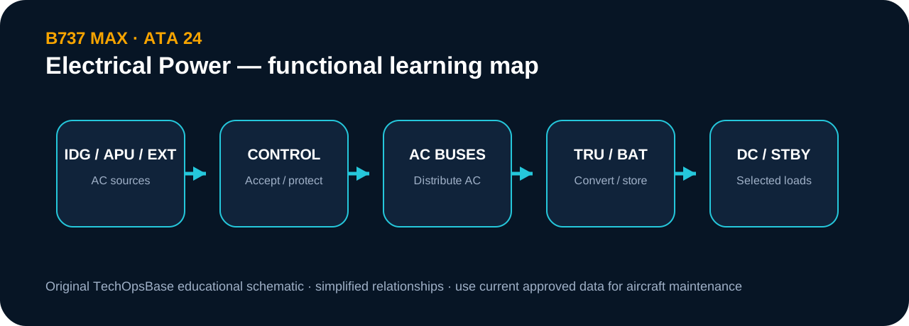
An original source-to-bus diagram linking IDGs, APU/external power, AC buses, TRUs, DC buses, battery and standby conversion.
Read from sources to loads
The diagram groups sources at the top, AC distribution in the middle, DC conversion/storage below and selected standby continuity to the side.
Use it to ask common-mode questions
If a group of loads is affected, move upstream through the map until their paths meet. That shared point becomes a useful hypothesis, not a maintenance conclusion.
Simplification is deliberate
The diagram omits exact contactor names, wiring, thresholds and effectivity-specific logic. Those remain in approved electrical and wiring data.
Evidence-first study method
For any system complaint, separate source/input, control logic, physical response, sensing/indication and consumer/result. When two layers disagree, that disagreement is useful evidence. Do not turn that evidence into a maintenance action until the applicable approved fault-isolation or maintenance data is open.
Approved-data boundary
Educational system explanation only. Do not use this page to perform maintenance, operate aircraft systems, isolate components or determine dispatch status. Current approved maintenance data, aircraft effectivity and operator procedures control real aircraft work.