Educational familiarization only. This is original TechOpsBase learning content. It does not reproduce Airbus pages, diagrams, procedures, maintenance-task instructions, numerical limits or controlled data. Actual aircraft work requires current approved data, correct aircraft effectivity, operator procedures, authorization, safety precautions and supervision.
Resource profile
- Aircraft: Airbus A350 family
- ATA chapter: 26 - Fire Protection
- Audience: Aviation enthusiasts, students, junior technicians and experienced maintainers
- Level: Intermediate system familiarization with maintenance reasoning
- Source basis: Privately supplied legacy manufacturer training and MSG-3 analysis
- Publication status: Draft pending technical review
Learning objectives
- Explain duct-type smoke detection.
- Describe airflow sampling through piccolo tubes.
- Trace detector pairs to CIDS warning logic.
- Connect smoke warning to ventilation and electrical isolation.
- Diagnose contamination and airflow-related faults.
1. Duct detector operating concept
Avionics, in-flight-entertainment and connectivity equipment are cooled by forced ventilation. Smoke generated inside a rack is carried into the extraction duct. Sampling the extraction flow allows the system to monitor a large equipment volume without placing one detector beside every electronic unit.
Duct-type detectors use a sealed sensing housing connected to the extraction duct through sample and return tubes. A piccolo tube collects representative airflow from the duct.
Detection performance depends on both detector health and ventilation airflow. A failed fan, blocked duct or disconnected sample tube can delay smoke transport even when the detector is electrically serviceable.

2. Detector pairs and CIDS logic
Pairs of smoke detectors provide redundant monitoring. The CIDS Smoke Detection Function evaluates detector state and generates a warning when both detect smoke, or when one detector is already inoperative and the remaining detector detects smoke.
The protected areas are identified separately: main avionics compartment, IFEC and connectivity rack. Warning and controlled-response functions depend on the affected area.
A common CIDS or power fault can affect several detector pairs. A blocked piccolo tube usually produces a local sampling problem.


3. Ventilation and electrical response
Smoke detection can command the Ventilation Control System to stop affected airflow. Cockpit controls allow the crew to isolate IFEC or connectivity ventilation and remove power from selected equipment.
Stopping ventilation reduces smoke movement and can remove the electrical source of the event, but it also changes airflow through the detector. Maintenance analysis must account for the commanded configuration.
A smoke warning can remain while equipment is isolated because particles remain in the duct or compartment.

4. Contamination and troubleshooting
Piccolo tubes and sample passages can collect dust and dirt. A blockage reduces representative air reaching the detector. Contamination inside the detector can produce sensitivity loss or nuisance warnings.
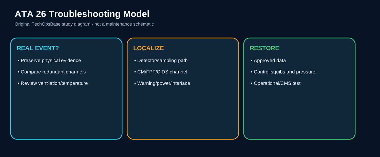
If both detectors in one extraction duct are reported failed, investigate shared power, airflow path, local wiring and CIDS interface. If one detector alone is failed, compare its sample tube, connector and internal status with its pair.
If an avionics smoke warning occurs with a cooling-fan fault, preserve the sequence. Reduced airflow may overheat equipment, while a genuine electrical event may have caused both smoke and fan shutdown.

Maintenance boundary
This resource teaches system architecture and fault reasoning. It deliberately excludes cartridge handling, squib isolation steps, bottle removal procedures, discharge tests, detector acceptance limits, resistance values, agent quantities, warning-reset procedures and dispatch decisions. Fire bottles, cartridges, squibs, hot-battery circuits and pressurized agent are hazardous. Use the current approved AMM, TSM, wiring data, safety procedures and aircraft effectivity before performing aircraft work.
Review prompts
- Which zone is being protected, and is the hazard fire, overheat or smoke?
- What sensing technology is used in that zone?
- Which independent channels must agree before a warning is confirmed?
- Which computing function converts, validates and distributes the signal?
- What automatic isolation or shutdown follows the warning?
- Is extinguishing automatic, manual, or not installed for that zone?
- Which test proves the detector path, warning path and firing-circuit monitoring?
- What hazardous stored energy remains during maintenance?