Educational familiarization only. This original TechOpsBase lesson was developed from privately supplied legacy A350 training and MSG-3 material. It does not reproduce manufacturer pages, proprietary diagrams, maintenance task steps, numerical maintenance limits, dispatch criteria or controlled maintenance data. Current approved aircraft data, correct effectivity, operator procedures and authorization govern all aircraft work.
Resource profile
- Aircraft: Airbus A350 family
- ATA chapter: 36 - Pneumatic
- Resource: A350 ATA 36 Maintenance and Troubleshooting Workshop
- Audience: Enthusiasts, students, junior technicians and professionals
- Level: Intermediate-to-advanced
- Status: Draft pending technical review
Learning objectives
- Build a safe diagnostic plan.
- Separate source, distribution and user faults.
- Use sensor and valve evidence correctly.
- Distinguish real leak from loop failure.
- Verify complete restoration and protection.
1. Purpose and operational value
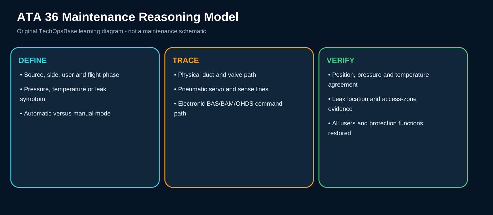
The workshop applies source-side-user, command-feedback-effect and physical-versus-electronic reasoning to realistic ATA 36 complaints.
2. Architecture and system flow
Begin by defining the aircraft configuration: ground or flight, active sources, crossbleed selector, user demand and recent control changes.
Capture first-fault messages, pressure and temperature indications, valve states, loop condition and leak-location data before reset when safe.
Build two parallel fault trees: the physical pneumatic path and the electronic/pneumatic command path. Join them only after command, feedback and physical effect are compared.
Use left/right symmetry, automatic/manual control and primary/backup monitoring as deliberate diagnostic comparisons.
3. Major components and functions
Configuration record
Defines source, side, user, phase and selector state. It must receive the correct pneumatic or electronic input, perform the expected function and return a believable output or status. A fault can result from electrical power, data communication, a blocked or leaking pressure/sense line, pneumatic contamination, mechanical friction, incorrect configuration, a failed sensor or an upstream/downstream system request. Useful evidence includes cockpit controls, BLEED page, active demand and recent transitions. A maintenance conclusion is strongest when command, feedback and physical pneumatic effect agree.
Physical air-path test
Checks pressure, temperature, flow, leakage and restrictions. It must receive the correct pneumatic or electronic input, perform the expected function and return a believable output or status. A fault can result from electrical power, data communication, a blocked or leaking pressure/sense line, pneumatic contamination, mechanical friction, incorrect configuration, a failed sensor or an upstream/downstream system request. Useful evidence includes test-set data, downstream response and local inspection. A maintenance conclusion is strongest when command, feedback and physical pneumatic effect agree.
Command-path analysis
Checks BAS, BAM, BOMU, CRDC, servo and valve commands. It must receive the correct pneumatic or electronic input, perform the expected function and return a believable output or status. A fault can result from electrical power, data communication, a blocked or leaking pressure/sense line, pneumatic contamination, mechanical friction, incorrect configuration, a failed sensor or an upstream/downstream system request. Useful evidence includes BITE, command, feedback and shared-resource grouping. A maintenance conclusion is strongest when command, feedback and physical pneumatic effect agree.
OHDS analysis
Separates loop failure, true heat and unsuccessful isolation. It must receive the correct pneumatic or electronic input, perform the expected function and return a believable output or status. A fault can result from electrical power, data communication, a blocked or leaking pressure/sense line, pneumatic contamination, mechanical friction, incorrect configuration, a failed sensor or an upstream/downstream system request. Useful evidence includes loop health, zone, isolation attempts and CMS location. A maintenance conclusion is strongest when command, feedback and physical pneumatic effect agree.
Restoration test
Proves regulation, distribution, indication and protection. It must receive the correct pneumatic or electronic input, perform the expected function and return a believable output or status. A fault can result from electrical power, data communication, a blocked or leaking pressure/sense line, pneumatic contamination, mechanical friction, incorrect configuration, a failed sensor or an upstream/downstream system request. Useful evidence includes all relevant sources/users, leak tightness and correct normal configuration. A maintenance conclusion is strongest when command, feedback and physical pneumatic effect agree.
4. Normal operating sequence
1. Make safe
Depressurize/cool/isolate according to approved data.
2. Preserve
Save first-fault and original configuration.
3. Compare
Use opposite side, alternate source and manual/automatic paths.
4. Localize
Identify source, valve, sensor, duct, controller or user interface.
5. Verify
Test full operating modes and protection after repair.
5. Control, monitoring and protection
Temporary recovery after reset or source change is not proof of repair.
A real hot-air leak can damage equipment outside ATA 36; inspection boundaries must follow approved data.
A valve replacement is incomplete until remote-servo lines, electrical channels, position feedback and leak tightness are verified.
6. Failure modes and maintenance reasoning
- Low pressure one side: Source, MPV/HPV, servo, sensor, isolation or duct restriction.
- High temperature one side: FAV, precooler, fan airflow, sensor or demand.
- Crossbleed disagreement: Command path, motor, sensor, mechanical jam or duct effect.
- Overheat message: True leak, loop fault, isolation failure or residual heat.
- Several indications lost: Shared CPIOM/BOMU/CRDC/power.
- Repeat fault after component change: Installation, sense line, configuration or upstream cause.
7. Interfaces with other systems
- AMM/TSM/CMS and approved test equipment.
- ATA 21/24/30/31/42/45/49/80.
- Aircraft structure and common installation.
- Operational/dispatch control.
8. Practical maintenance scenarios
Pressure low at idle only
Focus on HP-source selection, HPV command and pressure sensing.
Temperature high with fan-air valve apparently open
Confirm actual cooling airflow and precooler performance.
AUTO crossbleed fails, manual succeeds
Localize normal BAS/AFDX/CRDC control.
Leak warning clears after isolation but repeats next flight
Inspect the stored location, duct installation and sensing loops.
Multiple ATA alerts share one CPIOM/BOMU
Treat common control resource before system-specific LRUs.
9. Technician takeaways
- Map before replacing.
- Command, feedback and physical effect must agree.
- Use redundancy as diagnostic comparison.
- Verify protection as well as normal supply.
Maintenance boundary
This resource explains system architecture, normal operation, indication and maintenance reasoning. It intentionally excludes removal/installation procedures, wiring-pin checks, valve rigging, leak-test limits, servicing limits, maintenance intervals, software part numbers, dispatch decisions and release-to-service criteria.
Review prompts
- Which pneumatic source should be available in this configuration?
- Which valve or controller establishes the expected flow path?
- Which pressure, temperature or position feedback proves the command was achieved?
- Is the symptom local to one side, one source, one user or the complete manifold?
- Could a user-system demand or isolation command explain the observed state?
- Is the fault in the physical air path, the pneumatic control path or the electronic command path?
- What evidence must be preserved before reset, source change or manual override?
- What hot-air, pressure, moving-equipment and structural-protection boundary applies?