Educational familiarization only. This is original TechOpsBase learning content. It does not reproduce Airbus pages, diagrams, procedures, maintenance-task instructions, numerical limits or controlled data. Actual aircraft work requires current approved data, correct aircraft effectivity, operator procedures, authorization, safety precautions and supervision.
Resource profile
- Aircraft: Airbus A350 family
- ATA chapter: 26 - Fire Protection
- Audience: Aviation enthusiasts, students, junior technicians and experienced maintainers
- Level: Intermediate system familiarization with maintenance reasoning
- Source basis: Privately supplied legacy manufacturer training and MSG-3 analysis
- Publication status: Draft pending technical review
Learning objectives
- Identify the two MLG-bay protected zones.
- Explain the detector-loop arrangement and shared conversion module.
- Describe warning and degraded-loop logic.
- Explain why no extinguishing system is installed.
- Apply MLG-bay fire-warning troubleshooting.
1. Why the MLG bay is monitored
The main landing-gear bay contains hydraulic lines, electrical wiring, landing-gear structures and components exposed to brake and tire heat after landing. A fluid leak, electrical fault or overheated wheel/brake condition can create a serious fire or overheat hazard.
The bay is divided into left and right monitored zones. Each side has one detector from loop A and one corresponding detector from loop B. This arrangement provides side identification and redundant confirmation.
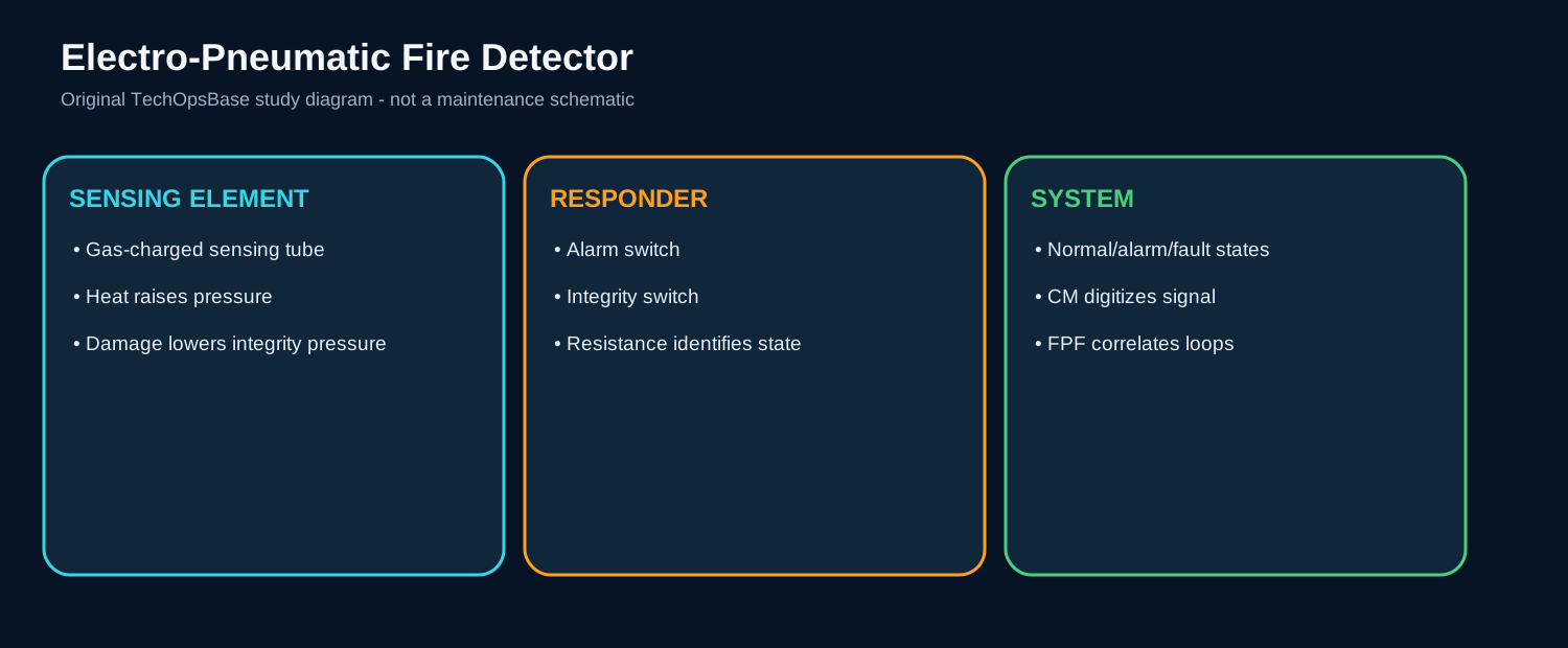
The detectors use the same electro-pneumatic principle as the engine and APU detectors, allowing normal, alarm and integrity-fault states to be distinguished.

2. Shared conversion architecture
MLG-bay detector loops connect to the APU/MLG-bay Conversion Module. The module digitizes detector states and sends them to FPF applications hosted in two computing channels.
Sharing the conversion module creates a diagnostic relationship: a module or common-interface fault can affect both APU and MLG-bay protection. Local wiring and detector faults remain zone specific.
Maintenance should compare APU and MLG-bay channel status when a conversion-module fault is suspected.

3. Warning logic and important boundary
For a bay side with both loops healthy, the fire or overheat warning is confirmed when both loops detect the event. If one loop is already failed, the remaining healthy loop can generate the warning.
Validated detection is sent through the FWS to master warning, warning display and MLG-bay indication. The common FIRE TEST exercises MLG-bay detection together with engine and APU protection.
The A350 MLG bay has detection and warning but no installed agent-discharge system. The operational response therefore depends on approved crew and ground procedures, aircraft movement and emergency services.


4. Troubleshooting and inspection
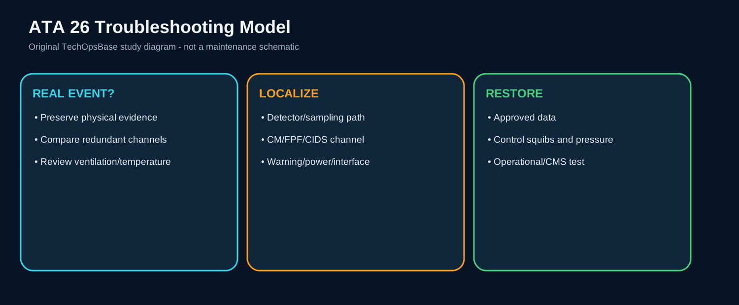
A bay warning shortly after landing may correlate with brake or tire heat, hydraulic leakage, wiring damage or foreign material. Review wheel/brake indications and related ATA 32 evidence without assuming the detector is reacting to normal heat.
If only one side or one loop is affected, inspect local detector routing, supports, wiring and possible contact with hot structure. If both MLG zones and APU detection show channel faults, investigate shared conversion or power paths.
Do not enter the bay until landing gear, doors, hydraulics, electrical power and fire-protection firing circuits are made safe. Confirm all protective covers and detector supports are restored after access.

Maintenance boundary
This resource teaches system architecture and fault reasoning. It deliberately excludes cartridge handling, squib isolation steps, bottle removal procedures, discharge tests, detector acceptance limits, resistance values, agent quantities, warning-reset procedures and dispatch decisions. Fire bottles, cartridges, squibs, hot-battery circuits and pressurized agent are hazardous. Use the current approved AMM, TSM, wiring data, safety procedures and aircraft effectivity before performing aircraft work.
Review prompts
- Which zone is being protected, and is the hazard fire, overheat or smoke?
- What sensing technology is used in that zone?
- Which independent channels must agree before a warning is confirmed?
- Which computing function converts, validates and distributes the signal?
- What automatic isolation or shutdown follows the warning?
- Is extinguishing automatic, manual, or not installed for that zone?
- Which test proves the detector path, warning path and firing-circuit monitoring?
- What hazardous stored energy remains during maintenance?