Educational familiarization only. This is original TechOpsBase learning content. It does not reproduce Airbus pages, diagrams, procedures, maintenance-task instructions, numerical limits or controlled data. Actual aircraft work requires current approved data, correct aircraft effectivity, operator procedures, authorization, safety precautions and supervision.
Resource profile
- Aircraft: Airbus A350 family
- ATA chapter: 26 - Fire Protection
- Audience: Aviation enthusiasts, students, junior technicians and experienced maintainers
- Level: Intermediate system familiarization with maintenance reasoning
- Source basis: Privately supplied legacy manufacturer training and MSG-3 analysis
- Publication status: Draft pending technical review
Learning objectives
- Explain the two functions of engine fire extinguishing.
- Trace the fire-control isolation chain.
- Describe the two-bottle discharge architecture.
- Explain bottle-pressure and squib-continuity monitoring.
- Recognize energetic-device and hot-battery hazards.
1. Extinguishing and isolation
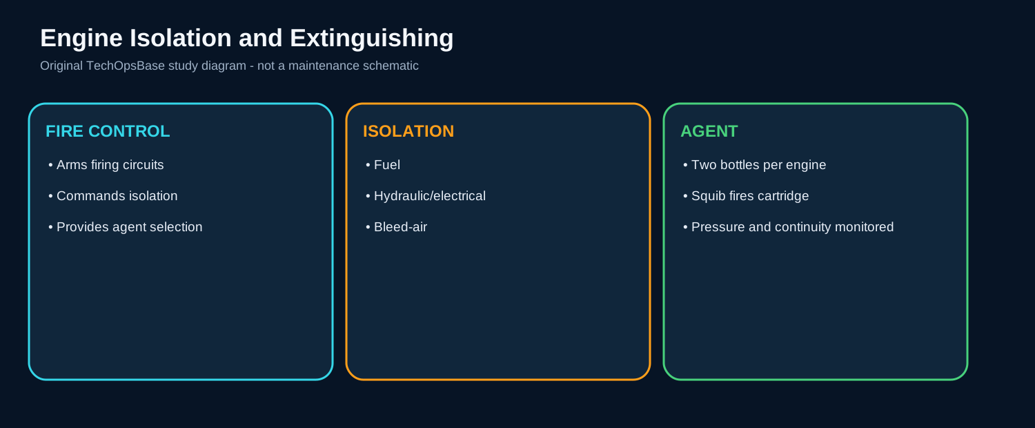
The engine fire-extinguishing system has two complementary purposes. It delivers extinguishing agent into protected engine zones, and it isolates the engine from sources that can sustain or spread fire. Agent discharge without fuel, hydraulic, bleed-air and electrical isolation may not control the event.
The isolation function is initiated through the engine fire control. Releasing the control arms the bottle firing circuits and commands the relevant aircraft systems to isolate the affected engine.
This architecture explains why a fire-control fault can be serious even when the bottles are serviceable. The control may fail to arm firing circuits, or one isolation command may not reach the associated system.
2. Two-bottle and firing architecture
Each engine has two extinguisher bottles. Two agents provide repeated attack capability and improve the probability of extinguishing a fire when one discharge is insufficient.
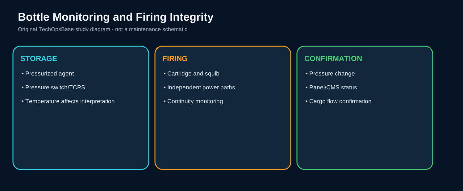
Each bottle contains pressurized extinguishing agent retained by a discharge assembly. An electrically fired cartridge ruptures the discharge path. The firing circuit is designed to remain available in severe electrical configurations and is supplied from hot-battery power.
A cartridge is an energetic device. Its squib converts electrical firing energy into mechanical rupture of the bottle discharge seal. Continuity monitoring checks the electrical firing path, but it does not prove agent quantity, plumbing condition or successful distribution.
3. Bottle-pressure monitoring
A bottle pressure switch provides an electrical indication of low pressure or discharge state. The signal is converted and sent through the FPF to cockpit indications and maintenance records.
Pressure indication is affected by bottle condition and temperature. A low-pressure indication may represent successful discharge, leakage, temperature-related behavior, pressure-switch failure, wiring or conversion-channel failure.
A bottle that appears physically intact can be unserviceable if charge pressure, cartridge continuity or distribution connections are incorrect. Conversely, an electrical low-pressure message must be confirmed before bottle replacement.

4. Failure modes and post-event reasoning
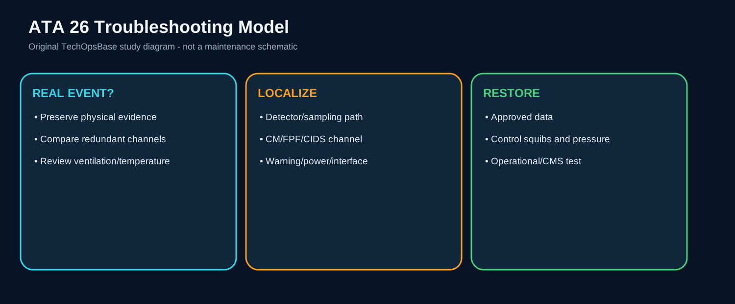
Failure to arm can originate in the fire control, interlock logic, FPF, power supply or wiring. Failure to isolate one fire source can originate in the commanded aircraft system rather than ATA 26 itself. Failure to discharge can involve the agent control, hot-battery path, squib, cartridge, bottle or distribution plumbing.
If a discharge indication appears without a commanded event, protect the area and establish whether an actual discharge occurred. Check pressure state, cartridge condition, fault history and wiring while respecting agent and energetic-device hazards.
After a real fire event, inspect the protected zone, isolation interfaces, detector loops, plumbing, nozzles and adjacent systems. Record which bottle discharged and identify the initiating leak or overheat source before resetting evidence.
Maintenance boundary
This resource teaches system architecture and fault reasoning. It deliberately excludes cartridge handling, squib isolation steps, bottle removal procedures, discharge tests, detector acceptance limits, resistance values, agent quantities, warning-reset procedures and dispatch decisions. Fire bottles, cartridges, squibs, hot-battery circuits and pressurized agent are hazardous. Use the current approved AMM, TSM, wiring data, safety procedures and aircraft effectivity before performing aircraft work.
Review prompts
- Which zone is being protected, and is the hazard fire, overheat or smoke?
- What sensing technology is used in that zone?
- Which independent channels must agree before a warning is confirmed?
- Which computing function converts, validates and distributes the signal?
- What automatic isolation or shutdown follows the warning?
- Is extinguishing automatic, manual, or not installed for that zone?
- Which test proves the detector path, warning path and firing-circuit monitoring?
- What hazardous stored energy remains during maintenance?