Educational familiarization only. This is original TechOpsBase learning content. It does not reproduce Airbus pages, diagrams, procedures, maintenance-task instructions, numerical limits or controlled data. Actual aircraft work requires current approved data, correct aircraft effectivity, operator procedures, authorization, safety precautions and supervision.
Resource profile
- Aircraft: Airbus A350 family
- ATA chapter: 26 - Fire Protection
- Audience: Aviation enthusiasts, students, junior technicians and experienced maintainers
- Level: Intermediate system familiarization with maintenance reasoning
- Source basis: Privately supplied legacy manufacturer training and MSG-3 analysis
- Publication status: Draft pending technical review
Learning objectives
- Identify the engine fire-protection zones and detector coverage.
- Explain engine loop-A and loop-B signal processing.
- Describe warning logic with healthy and degraded loops.
- Interpret engine detector and channel failures.
- Apply zone-based maintenance reasoning.
1. Engine fire-zone philosophy
The engine nacelle and pylon are divided into protected zones because heat sources, ventilation, fluid lines and fire consequences differ across the installation. The fan compartment is monitored with broad left and right coverage. The intermediate-pressure compressor region has dedicated sensing. The core and pylon areas are included in the rear protection zone.
Zone division allows the system to correlate detector alarms in the same physical area and helps maintenance identify where to inspect. Airflow, temperature, detector length, supports and possible leakage sources differ between zones.
A detected overheat can be operationally significant even before flame exists. Hot bleed-air leakage, oil leakage onto hot structure, fuel leakage, damaged insulation or abnormal component temperature can raise the detector response. Maintenance should investigate the heat source, not only the detector.

2. Loop installation and warning logic
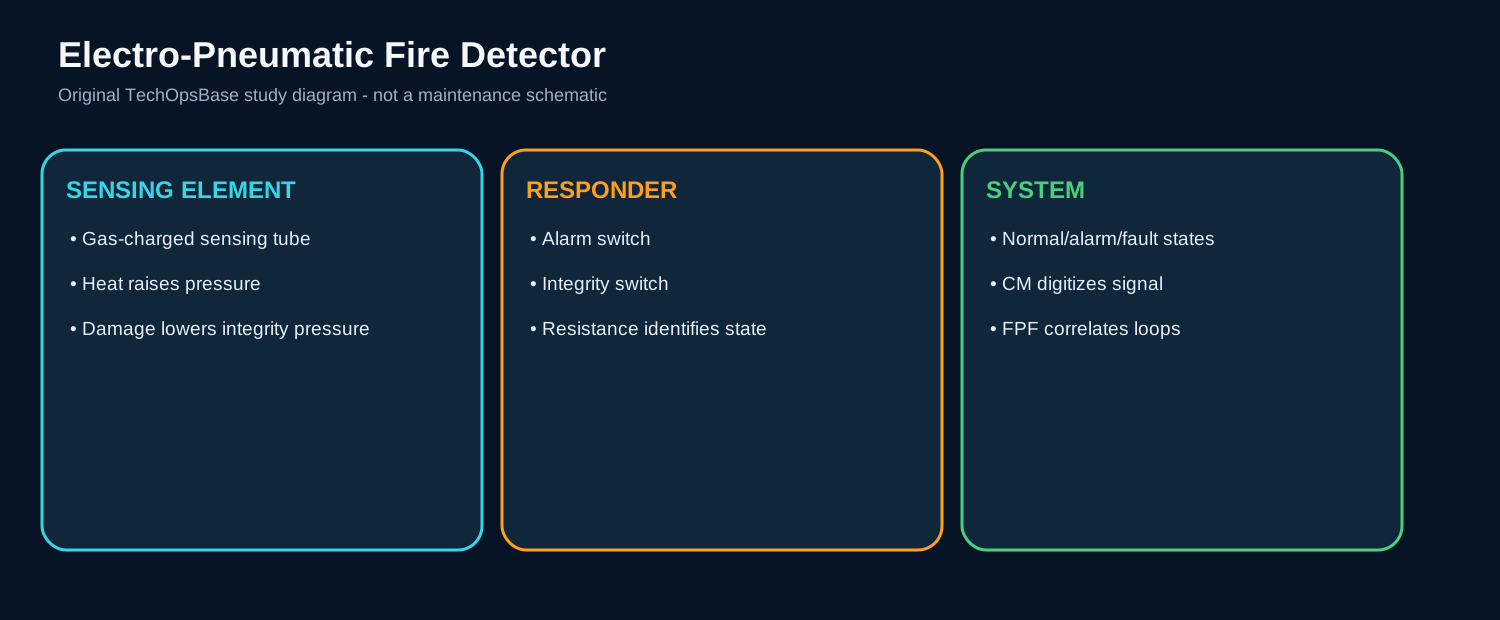
Each protected zone contains sensing elements belonging to loop A and corresponding elements belonging to loop B. One conversion channel serves each loop. Independent routing and computing reduce common-cause loss.
With both loops serviceable, engine fire warning requires corresponding detection by both loops in a common zone. If one loop is declared defective, detection from the remaining loop is accepted because waiting for agreement would remove protection entirely.
The detector is exposed to vibration, nacelle movement, heat cycling and maintenance access. Correct clamp location, bend radius, clearance, responder mounting and connector security are essential. A detector touching unintended hot structure can produce a real detector alarm that misrepresents the underlying fault.

3. Crew warning and maintenance evidence
Validated engine fire detection is sent through the FWS to master warnings, aural warning, warning display and engine-system presentation. The related engine fire control becomes the crew interface for isolation and extinguishing.
A display message is an interpreted result, not a raw detector measurement. Maintenance should review channel and detector details in the CMS before replacing hardware.
Fault history, flight phase, engine operating condition and related bleed, fuel, oil or electrical messages help separate a real overheat from a detector or channel fault.


4. Troubleshooting examples
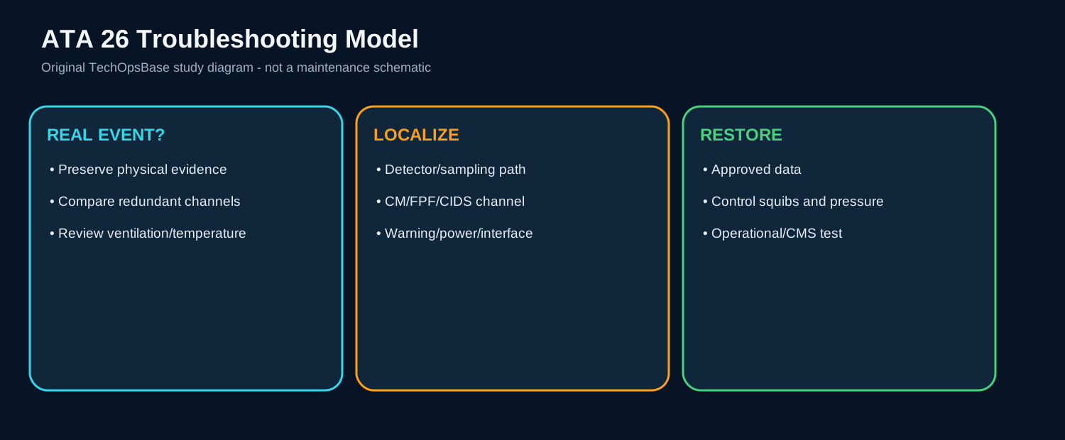
If one engine loop is failed with no fire indication, verify the affected zone and whether all detectors on that loop are lost. A complete-loop pattern suggests channel power, conversion or wiring. A single element suggests local detector or harness damage.
If a fire warning occurred during a known hot-air or fluid-leak event, inspect the relevant zone for thermal evidence, discoloration, insulation damage and residue. Do not assume the detector is faulty because the warning later cleared.
If the fire test fails one indication, separate detector logic from panel lamp, warning interface and test-command paths. If bottle monitoring also fails, look for a shared FPF, panel or power-path issue.
5. Inspection and verification
Inspect detector routing, clamps, sensing-element condition, responder security, connectors, wiring separation and heat shielding. Review nearby maintenance for accidental damage or incorrect installation.
Use approved detector and loop tests to verify resistance, continuity and channel response. Avoid unapproved heating or mechanical manipulation of the detector.
After rectification, confirm full dual-loop health, complete operational-test response, fault-record closure and correct restoration of nacelle access and detector supports.

Maintenance boundary
This resource teaches system architecture and fault reasoning. It deliberately excludes cartridge handling, squib isolation steps, bottle removal procedures, discharge tests, detector acceptance limits, resistance values, agent quantities, warning-reset procedures and dispatch decisions. Fire bottles, cartridges, squibs, hot-battery circuits and pressurized agent are hazardous. Use the current approved AMM, TSM, wiring data, safety procedures and aircraft effectivity before performing aircraft work.
Review prompts
- Which zone is being protected, and is the hazard fire, overheat or smoke?
- What sensing technology is used in that zone?
- Which independent channels must agree before a warning is confirmed?
- Which computing function converts, validates and distributes the signal?
- What automatic isolation or shutdown follows the warning?
- Is extinguishing automatic, manual, or not installed for that zone?
- Which test proves the detector path, warning path and firing-circuit monitoring?
- What hazardous stored energy remains during maintenance?