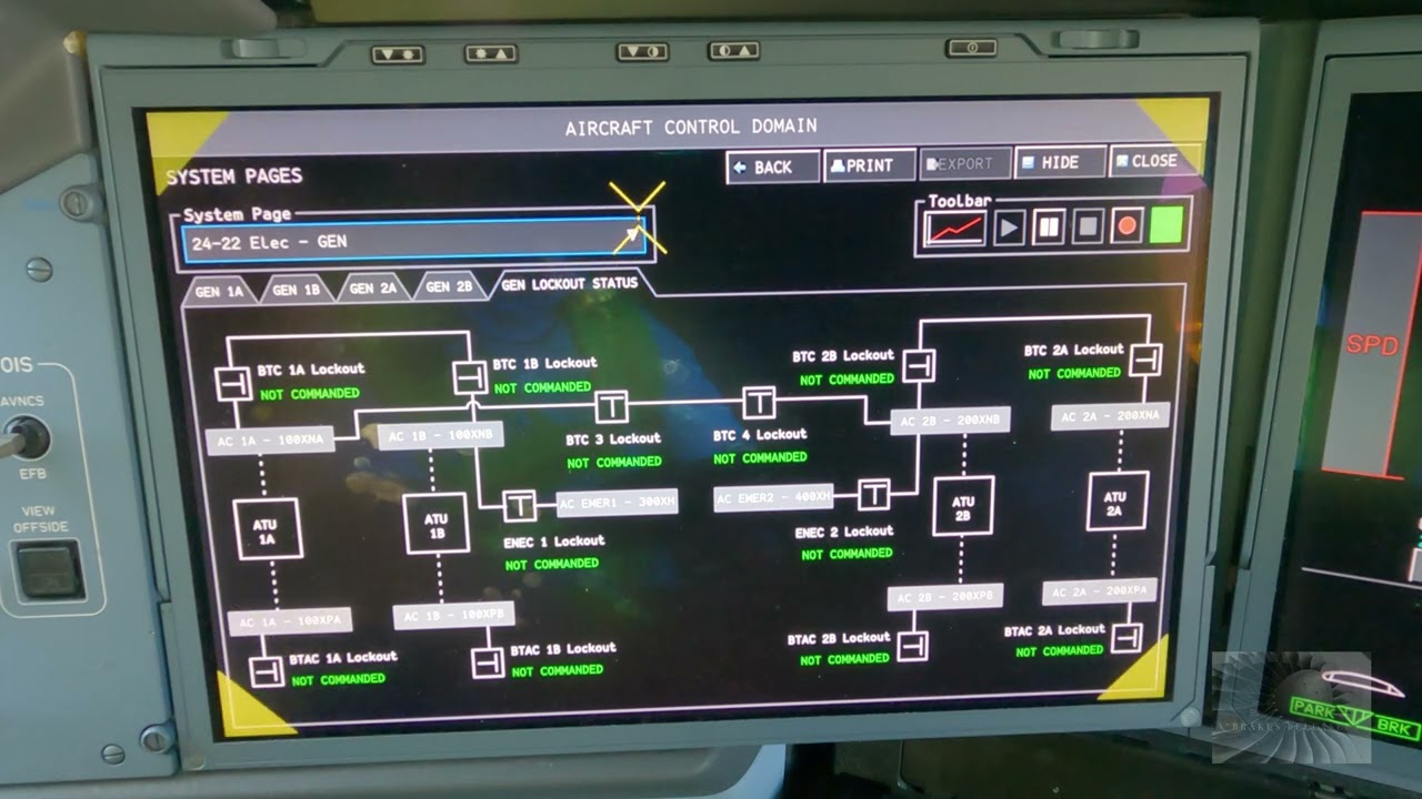
Educational familiarization only. This original TechOpsBase resource explains electrical-system purpose, architecture and maintenance reasoning. It does not reproduce Airbus pages, schematics, procedures, numerical limits or controlled maintenance data. Actual aircraft work requires current approved data, correct effectivity, operator procedures, authorization, safety precautions and supervision.
Resource profile
- Aircraft: Airbus A350 family
- ATA chapter: 24 — Electrical Power
- Audience: Students, junior technicians and working professionals
- Level: Intermediate familiarization
- Source basis: Privately supplied legacy manufacturer training and MSG-3 material
- Technical status: Draft pending technical review
Learning objectives
- Use source-to-load tracing.
- Separate source, control and distribution faults.
- Interpret reconfiguration.
- Recognize common-source failures.
- Apply electrical-safety controls.
1. Scenario: external power not available
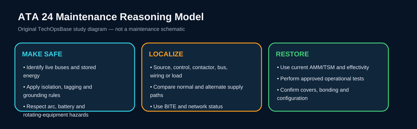
Check GPU output, cable and receptacle condition, source-quality validation, EPCU status, contactor command and related maintenance messages. Do not begin by replacing the receptacle or control unit without confirming the source.
If external power is available but will not connect, separate acceptance from contactor command and bus-interlock conditions.
2. Scenario: one engine generator lost
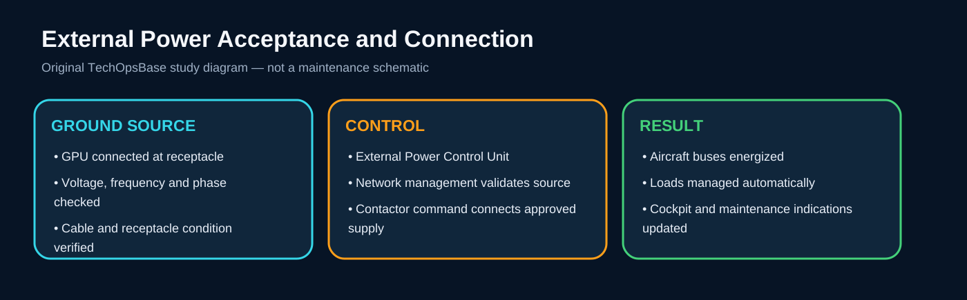
Confirm whether the generator is producing, whether protection disconnected it, whether the contactor opened, and which alternate source picked up the load. Review load shedding and bus-transfer status.
A successful transfer can hide the original fault from the crew while still leaving reduced redundancy.
3. Scenario: DC bus fault
Trace the bus back through its transformer rectifier, upstream AC supply, contactor and network command. Compare parallel DC channels and battery support.
A DC-bus failure can be caused by an AC-source loss, a conversion fault, distribution isolation or a bus short.

4. Scenario: battery warning
Review battery temperature, voltage, current, monitoring data, charging state and contactor configuration. Consider effectivity and chemistry before interpreting the fault.
Control thermal and electrical hazards before physical inspection.

5. Scenario: emergency configuration remains active
Determine whether normal sources have recovered, whether their quality is accepted, whether contactors can close and whether a fault remains latched. Verify which buses are intentionally shed.
Do not force reconnection outside the approved troubleshooting procedure.

Maintenance boundary
This lesson supports system understanding and maintenance reasoning. It deliberately excludes switching procedures, isolation steps, numerical limits, servicing values, connector pin data, torque values and configuration-specific dispatch decisions. Before working on the aircraft, confirm current approved maintenance data, aircraft effectivity, electrical-safety precautions, tooling, authorization and restoration requirements.
Review prompts
- Which power source should normally supply the affected bus?
- Which control unit validates and connects that source?
- Which contactor or conversion device lies in the power path?
- Which alternate source should be available?
- Which loads should remain powered, transfer or shed?
- Which indication proves source quality and which only proves contactor state?
- What stored-energy, arc, battery or grounding hazards remain after switches are turned off?