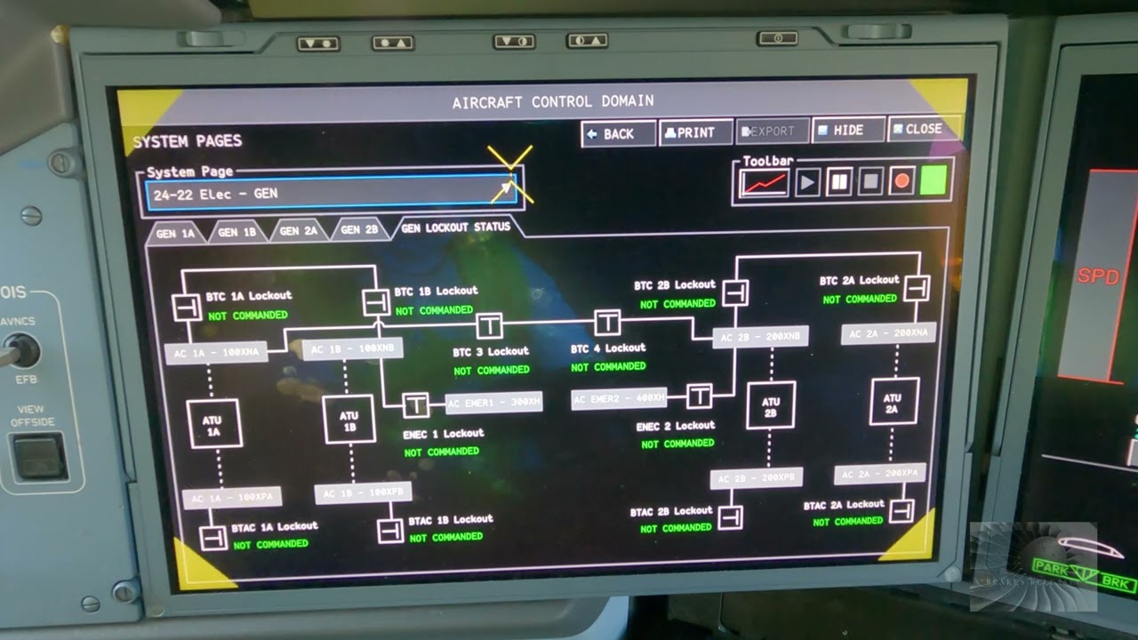
Educational familiarization only. This original TechOpsBase resource explains electrical-system purpose, architecture and maintenance reasoning. It does not reproduce Airbus pages, schematics, procedures, numerical limits or controlled maintenance data. Actual aircraft work requires current approved data, correct effectivity, operator procedures, authorization, safety precautions and supervision.
Resource profile
- Aircraft: Airbus A350 family
- ATA chapter: 24 — Electrical Power
- Audience: Students, junior technicians and working professionals
- Level: Intermediate familiarization
- Source basis: Privately supplied legacy manufacturer training and MSG-3 material
- Technical status: Draft pending technical review
Learning objectives
- Explain static-inverter purpose.
- Trace emergency battery input to AC output.
- Describe output monitoring and contactors.
- Recognize effectivity changes.
- Apply emergency-supply fault reasoning.
1. Purpose
The static inverter converts emergency DC power into AC power for selected critical consumers when the normal AC network is unavailable and before or alongside other emergency generation.
Its role is limited and prioritized. It does not recreate the complete normal AC network.

2. Input and conversion
Emergency-battery availability, control logic and contactor state determine whether the inverter receives DC input. Solid-state electronics then produce the required AC output for the inverter bus.
A no-output condition can originate in battery supply, input contactors, inverter electronics, output contactors, control logic or sensing.

3. Baseline architecture and monitoring
Legacy analysis material shows that the baseline architecture was reduced to one static inverter. That effectivity history matters because older references may show equipment no longer installed.
Maintenance should confirm aircraft configuration before using any schematic or component count.

4. Safety and testing
The inverter can create AC power even when normal generation is absent. Isolation planning must therefore include battery sources and inverter contactors.
Operational testing must follow current approved data because emergency-power tests can reconfigure multiple buses and loads.
Maintenance boundary
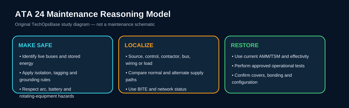
This lesson supports system understanding and maintenance reasoning. It deliberately excludes switching procedures, isolation steps, numerical limits, servicing values, connector pin data, torque values and configuration-specific dispatch decisions. Before working on the aircraft, confirm current approved maintenance data, aircraft effectivity, electrical-safety precautions, tooling, authorization and restoration requirements.
Review prompts
- Which power source should normally supply the affected bus?
- Which control unit validates and connects that source?
- Which contactor or conversion device lies in the power path?
- Which alternate source should be available?
- Which loads should remain powered, transfer or shed?
- Which indication proves source quality and which only proves contactor state?
- What stored-energy, arc, battery or grounding hazards remain after switches are turned off?