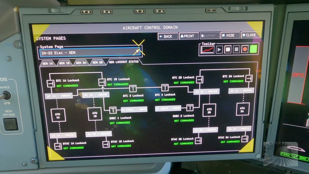
Educational familiarization only. This original TechOpsBase resource explains electrical-system purpose, architecture and maintenance reasoning. It does not reproduce Airbus pages, schematics, procedures, numerical limits or controlled maintenance data. Actual aircraft work requires current approved data, correct effectivity, operator procedures, authorization, safety precautions and supervision.
Resource profile
- Aircraft: Airbus A350 family
- ATA chapter: 24 — Electrical Power
- Audience: Students, junior technicians and working professionals
- Level: Intermediate familiarization
- Source basis: Privately supplied legacy manufacturer training and MSG-3 material
- Technical status: Draft pending technical review
Learning objectives
- Explain structural electrical return concepts.
- Differentiate bonding, grounding and earthing.
- Recognize resistance and corrosion risks.
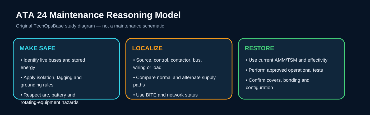
- Apply safe isolation.
- Verify restoration after maintenance.
1. Electrical structure network
The aircraft structure participates in controlled electrical return and bonding functions. Dedicated paths, bonding straps and designed interfaces maintain low-impedance connections across structures and equipment.
Damage, corrosion, paint, loose hardware or incorrect installation can increase resistance and create heating, electromagnetic-interference or lightning-protection concerns.
2. Bonding and grounding concepts
Bonding equalizes electrical potential between conductive parts. Grounding provides a controlled reference or return path. Earthing connects the aircraft to an external earth point for specific ground-maintenance or fueling conditions.
These terms are related but not interchangeable in a maintenance task.
3. Wiring and connector awareness
Electrical faults often originate in wiring, connectors, splices, shields or grounds rather than the controlled unit. Visual condition, security, contamination, chafing and correct routing matter.
Resistance or insulation tests must follow approved methods to avoid damaging sensitive electronics.

4. Restoration
After electrical work, confirm connector locking, backshells, shields, bonding straps, covers, clamps, routing, separation and foreign-object control.
A successful operational test does not excuse incomplete physical restoration.
Maintenance boundary
This lesson supports system understanding and maintenance reasoning. It deliberately excludes switching procedures, isolation steps, numerical limits, servicing values, connector pin data, torque values and configuration-specific dispatch decisions. Before working on the aircraft, confirm current approved maintenance data, aircraft effectivity, electrical-safety precautions, tooling, authorization and restoration requirements.
Review prompts
- Which power source should normally supply the affected bus?
- Which control unit validates and connects that source?
- Which contactor or conversion device lies in the power path?
- Which alternate source should be available?
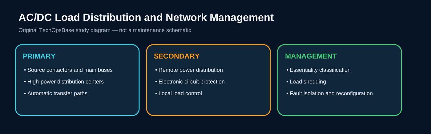
- Which loads should remain powered, transfer or shed?
- Which indication proves source quality and which only proves contactor state?
- What stored-energy, arc, battery or grounding hazards remain after switches are turned off?