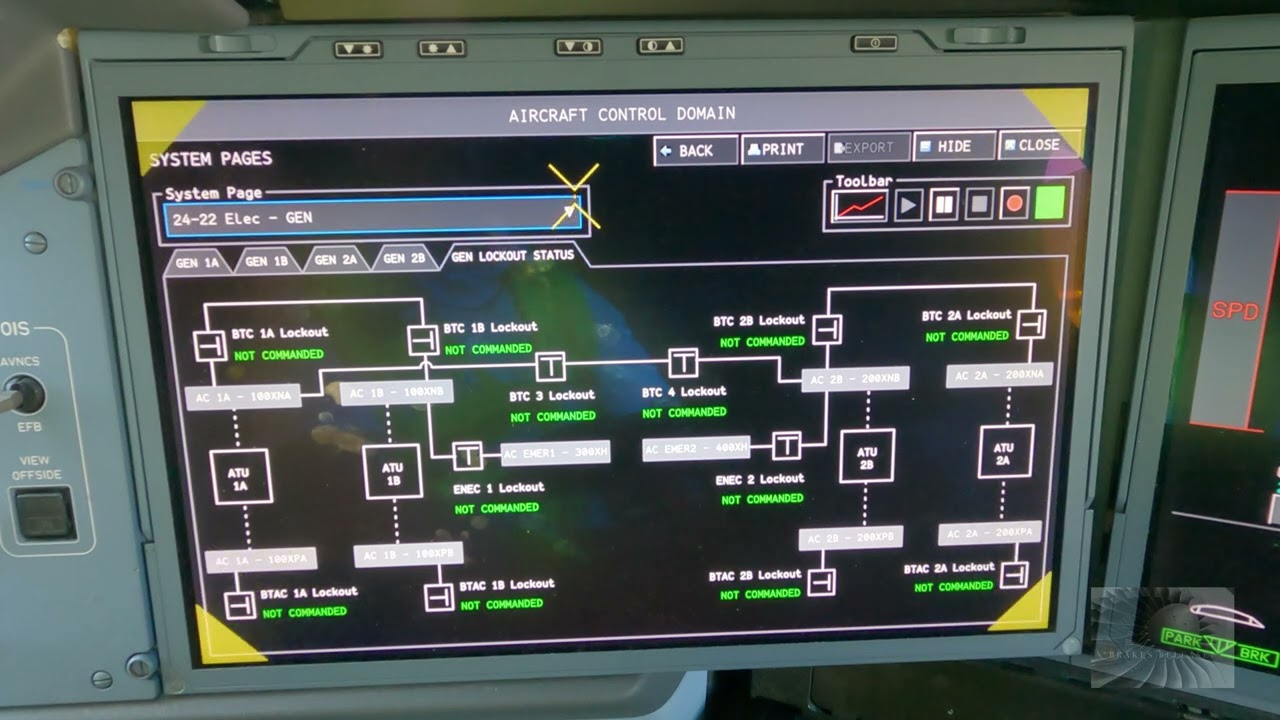
Educational familiarization only. This original TechOpsBase resource explains electrical-system purpose, architecture and maintenance reasoning. It does not reproduce Airbus pages, schematics, procedures, numerical limits or controlled maintenance data. Actual aircraft work requires current approved data, correct effectivity, operator procedures, authorization, safety precautions and supervision.
Resource profile
- Aircraft: Airbus A350 family
- ATA chapter: 24 — Electrical Power
- Audience: Students, junior technicians and working professionals
- Level: Intermediate familiarization
- Source basis: Privately supplied legacy manufacturer training and MSG-3 material
- Technical status: Draft pending technical review
Learning objectives
- Describe the emergency sequence.
- Explain battery bridging.
- Explain RAT AC generation.
- Connect emergency AC to emergency DC.
- Recognize intentionally shed loads.
1. Initial loss of normal generation
When normal AC generation is lost, batteries immediately preserve selected control and indication functions. The static inverter provides limited emergency AC power from emergency DC supply.
This bridge keeps critical systems alive while the RAT deploys and reaches operating condition.

2. RAT generation
The ram-air turbine drives an emergency AC generator. Once available, it supplies the emergency AC network subject to aircraft configuration and system logic.
RAT output is limited compared with normal generation, so the network continues to prioritize essential loads.

3. Emergency DC restoration
Emergency transformer rectifiers convert emergency AC power to DC for the emergency DC buses. Batteries remain part of the architecture for continuity and backup.
A fault in emergency DC supply may originate in the RAT AC path, the emergency TRs, battery contactors, distribution or control logic.

4. Maintenance reasoning
Emergency-power tests can deploy or simulate critical configurations and may affect flight-control, indication and communication systems. Use only approved procedures with the aircraft correctly prepared.
After actual RAT deployment, stowage and restoration require dedicated maintenance action.
Maintenance boundary
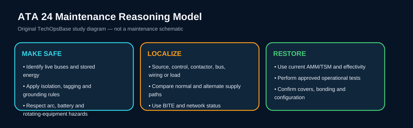
This lesson supports system understanding and maintenance reasoning. It deliberately excludes switching procedures, isolation steps, numerical limits, servicing values, connector pin data, torque values and configuration-specific dispatch decisions. Before working on the aircraft, confirm current approved maintenance data, aircraft effectivity, electrical-safety precautions, tooling, authorization and restoration requirements.
Review prompts
- Which power source should normally supply the affected bus?
- Which control unit validates and connects that source?
- Which contactor or conversion device lies in the power path?
- Which alternate source should be available?
- Which loads should remain powered, transfer or shed?
- Which indication proves source quality and which only proves contactor state?
- What stored-energy, arc, battery or grounding hazards remain after switches are turned off?