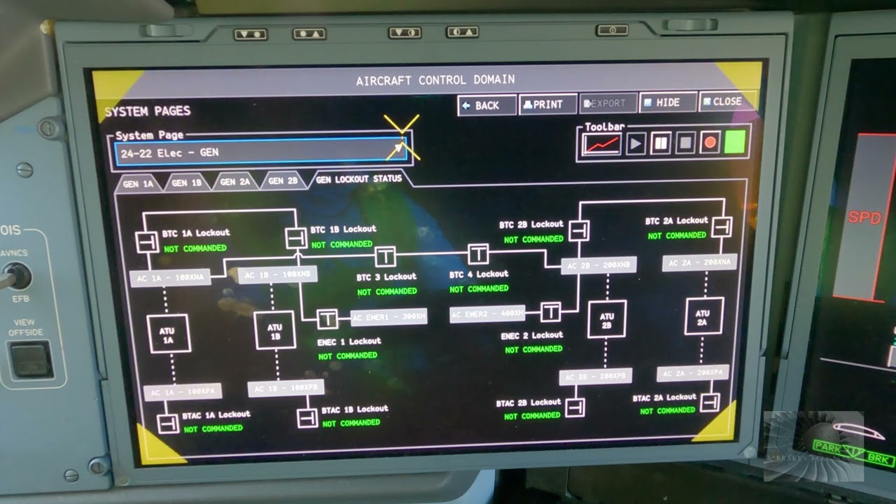
Educational familiarization only. This original TechOpsBase resource explains electrical-system purpose, architecture and maintenance reasoning. It does not reproduce Airbus pages, schematics, procedures, numerical limits or controlled maintenance data. Actual aircraft work requires current approved data, correct effectivity, operator procedures, authorization, safety precautions and supervision.
Resource profile
- Aircraft: Airbus A350 family
- ATA chapter: 24 — Electrical Power
- Audience: Students, junior technicians and working professionals
- Level: Intermediate familiarization
- Source basis: Privately supplied legacy manufacturer training and MSG-3 material
- Technical status: Draft pending technical review
Learning objectives
- Explain external-power acceptance.
- Trace GPU power to aircraft buses.
- Describe EPCU and contactor roles.
- Recognize unsafe connection conditions.
- Apply ground-power troubleshooting.
1. Ground source and receptacles
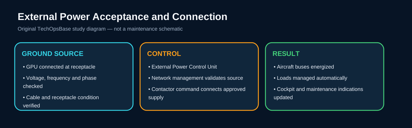
External power allows the aircraft to be energized without engine or APU generation. The GPU must provide acceptable electrical quality and be connected through serviceable cables and receptacles.
Physical connection alone does not mean the source is accepted or connected.
2. Validation and connection
External Power Control Units and network-management logic evaluate source quality and command the appropriate contactors. Voltage, frequency, phase and wiring conditions must be acceptable before the source is connected.
An EXT PWR available indication generally means quality checks passed; a connected indication additionally depends on command and contactor state.

3. Source priority and load pickup
When external power is connected on the ground, the network determines which buses and loads can be supplied and whether other sources should remain isolated.
High initial load, poor GPU regulation, cable voltage drop or contactor problems can cause repeated connection and disconnection.

4. Ground safety
Inspect plugs, pins, cable strain, contamination, heat damage and receptacle security. Follow the approved connect/disconnect sequence and communication with ground personnel.
External power can energize systems unexpectedly. Maintenance configuration, warning tags and personnel clearance must be controlled before connection.
Maintenance boundary
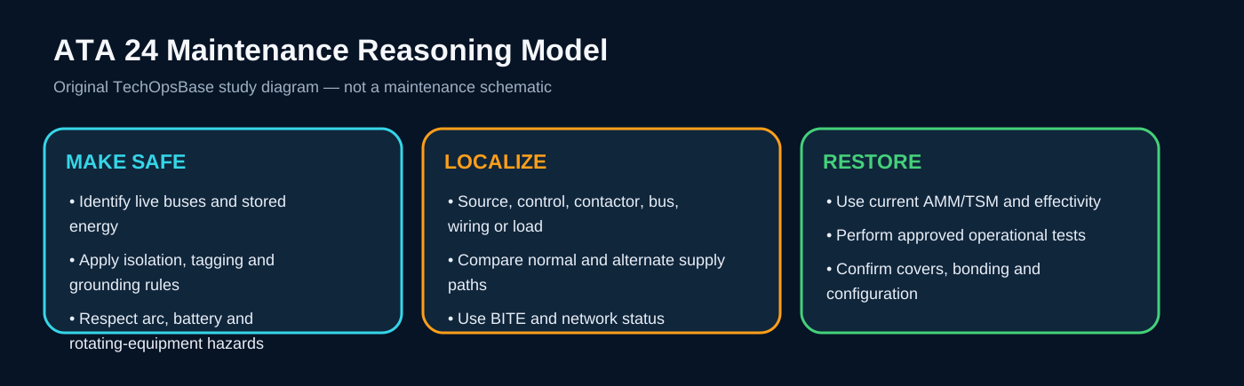
This lesson supports system understanding and maintenance reasoning. It deliberately excludes switching procedures, isolation steps, numerical limits, servicing values, connector pin data, torque values and configuration-specific dispatch decisions. Before working on the aircraft, confirm current approved maintenance data, aircraft effectivity, electrical-safety precautions, tooling, authorization and restoration requirements.
Review prompts
- Which power source should normally supply the affected bus?
- Which control unit validates and connects that source?
- Which contactor or conversion device lies in the power path?
- Which alternate source should be available?
- Which loads should remain powered, transfer or shed?
- Which indication proves source quality and which only proves contactor state?
- What stored-energy, arc, battery or grounding hazards remain after switches are turned off?