Educational familiarization only. This original TechOpsBase resource explains system purpose, architecture and maintenance reasoning. It does not reproduce Airbus pages, diagrams, procedures, limits or controlled maintenance data. Actual aircraft work requires current approved data, correct effectivity, operator procedures, authorization, safety precautions and supervision.
Resource profile
- Aircraft: Airbus A350 family
- ATA chapter: 32 — Landing Gear
- Audience: Students, junior technicians and working professionals
- Level: Intermediate familiarization
- Source basis: Privately supplied legacy manufacturer training and MSG-3 material
- Technical status: Draft pending technical review
Learning objectives
- Use command-versus-response reasoning.
- Interpret gear, brake and steering indications.
- Identify hidden backup degradation.
- Control stored-energy and movement hazards.
- Work through integrated scenarios.
1. Evidence hierarchy
Good troubleshooting uses multiple evidence sources: physical configuration, cockpit indications, system pages, maintenance messages, recorded fault history, hydraulic pressure, electrical status and approved operational tests. One message rarely proves one component failed.
Start with the operational symptom and the last known correct state. Then determine whether the failure is local, side-specific, gear-specific or common to several functions.

2. Physical safing
ATA 32 contains major movement, stored-pressure, heat and aircraft-stability hazards. Gear and door pins, jacks, chocks, brake cooling, accumulator pressure, towing configuration and hydraulic isolation must be controlled before troubleshooting begins.
Administrative confirmation is not enough. Physically verify installed safety devices and the aircraft condition required by the task.

3. Scenario: one gear remains unsafe
Separate actual incomplete travel from a sensing disagreement. Confirm door and lock state, compare hydraulic and electrical conditions, identify the last completed sequence step and inspect for obstruction or abnormal geometry only under approved safe access.
Do not repeatedly cycle the gear in an attempt to clear the indication.

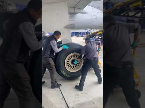
4. Scenario: weak or asymmetric braking
Compare pedal or autobrake demand, active braking mode, wheel-speed data, pressure command, hydraulic source and brake condition. Consider tire/runway effects and temperature. A single wheel-speed fault can alter anti-skid behavior without a hydraulic leak.
If multiple wheel groups are affected, look for shared power, computer or hydraulic sources before replacing local components.

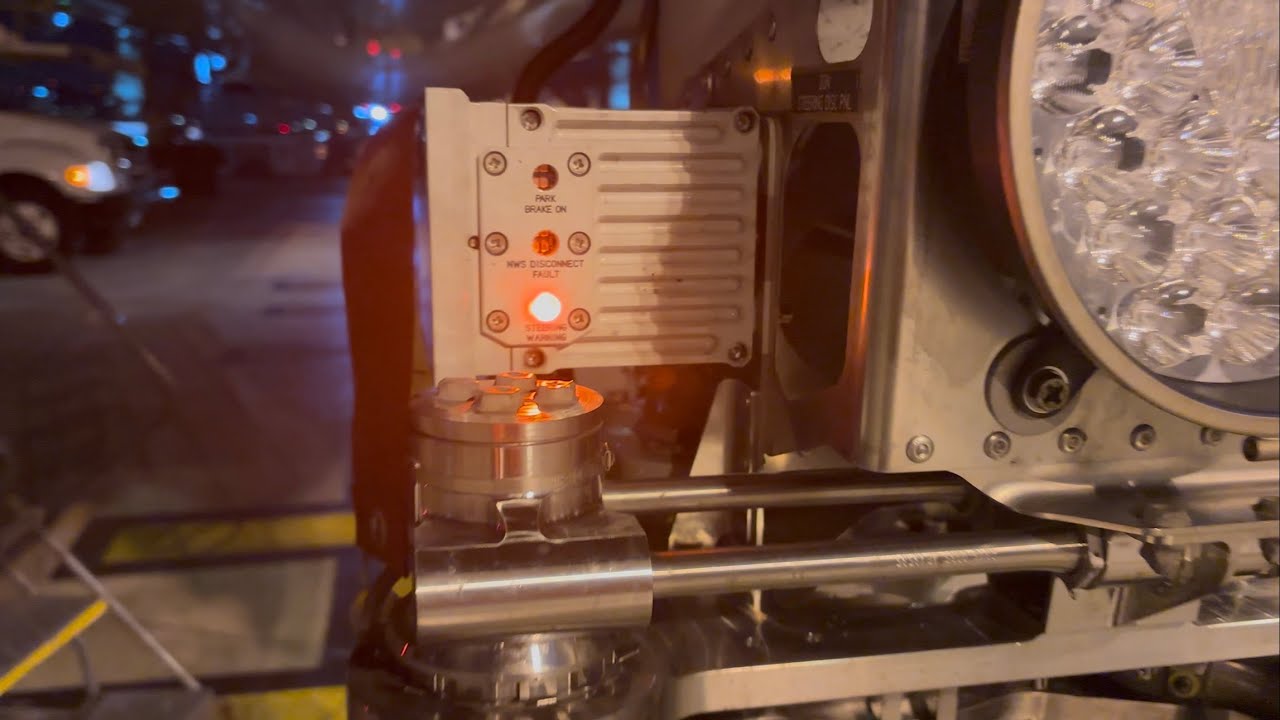
5. Scenario: steering unavailable
Verify towing/disconnect configuration, speed and aircraft-state inputs, command-source validity, hydraulic availability, steering-computer status and angle feedback. Then inspect the mechanical path if commanded and actual motion differ.
After rectification, perform the approved operational test and confirm correct centering and retraction interface.

Maintenance boundary
This lesson supports system understanding and maintenance reasoning. It deliberately excludes task steps, numerical limits, servicing quantities, torque values, dispatch decisions and configuration-specific instructions. Before touching the aircraft, confirm the current approved maintenance data, aircraft effectivity, safety procedures, tooling, personnel authorization and restoration requirements.
Review prompts
- What is the commanded function?
- Which computer or control channel accepts the command?
- Which energy source performs the movement or braking action?
- Which mechanical locks, valves or actuators must change state?
- Which sensors confirm that the commanded state was achieved?
- What independent or alternate path remains available?
- What hazards exist if maintenance personnel assume the indication alone proves the system is safe?