Educational familiarization only. This original TechOpsBase resource explains system purpose, architecture and maintenance reasoning. It does not reproduce Airbus pages, diagrams, procedures, limits or controlled maintenance data. Actual aircraft work requires current approved data, correct effectivity, operator procedures, authorization, safety precautions and supervision.
Resource profile
- Aircraft: Airbus A350 family
- ATA chapter: 32 — Landing Gear
- Audience: Students, junior technicians and working professionals
- Level: Intermediate familiarization
- Source basis: Privately supplied legacy manufacturer training and MSG-3 material
- Technical status: Draft pending technical review
Learning objectives
- Identify NLG structural components.
- Explain retraction and locking.
- Connect centering to safe retraction.
- Relate NLG mechanics to steering.
- Apply safe maintenance reasoning.
1. Nose-gear functions
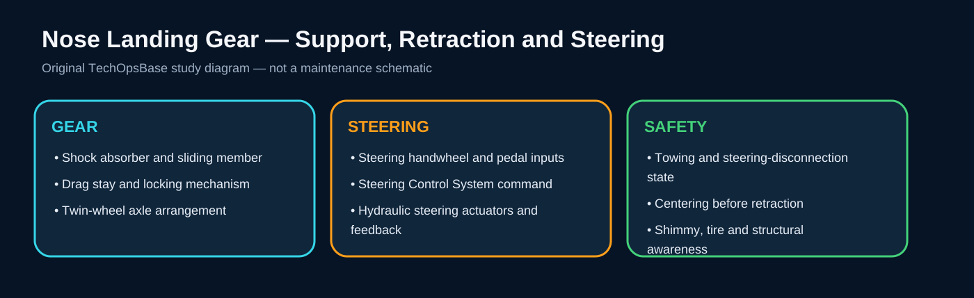
The nose landing gear supports the forward fuselage, absorbs ground loads and provides directional control during taxi. Its shock absorber, sliding tube, torque links, axle and twin wheels must remain structurally aligned while allowing vertical movement and steering rotation.
Unlike the main gears, the nose gear must combine retraction geometry with a large steering range. This creates interfaces between the landing-gear extension/retraction system and the steering-control system.
2. Locking and retraction
The drag-stay and lock-link arrangement stabilizes the extended gear. A lock-link actuator releases the geometry for retraction. The retraction actuator then moves the gear into the bay, where an uplock holds it.
The wheels must be centered before they enter the bay. A centering fault can therefore inhibit or complicate retraction even when hydraulic pressure and the retraction actuator are available.

3. Steering and towing interfaces
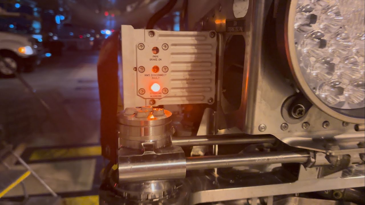
Steering commands are accepted only under appropriate aircraft conditions. Towing configuration must prevent unwanted powered steering and protect the mechanical linkage. Incorrect tow-pin or disconnect configuration can produce damage or misleading steering faults.
Maintenance should distinguish tire scrub, mechanical stiffness, hydraulic actuator behavior, command limitation and feedback-sensor disagreement.

4. Maintenance awareness
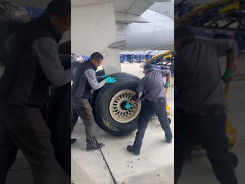
Key concerns include shock-absorber condition, torque-link wear, steering collar and actuator security, tire condition, wheel bearings, lock geometry, door clearances, centering and position sensing.
Any work near the NLG requires control of aircraft movement, steering energy, towing state and personnel position. Nose-wheel movement can occur suddenly when hydraulic or electrical power is restored.

Maintenance boundary
This lesson supports system understanding and maintenance reasoning. It deliberately excludes task steps, numerical limits, servicing quantities, torque values, dispatch decisions and configuration-specific instructions. Before touching the aircraft, confirm the current approved maintenance data, aircraft effectivity, safety procedures, tooling, personnel authorization and restoration requirements.
Review prompts
- What is the commanded function?
- Which computer or control channel accepts the command?
- Which energy source performs the movement or braking action?
- Which mechanical locks, valves or actuators must change state?
- Which sensors confirm that the commanded state was achieved?
- What independent or alternate path remains available?
- What hazards exist if maintenance personnel assume the indication alone proves the system is safe?