Educational familiarization only. This original TechOpsBase resource explains system purpose, architecture and maintenance reasoning. It does not reproduce Airbus pages, diagrams, procedures, limits or controlled maintenance data. Actual aircraft work requires current approved data, correct effectivity, operator procedures, authorization, safety precautions and supervision.
Resource profile
- Aircraft: Airbus A350 family
- ATA chapter: 32 — Landing Gear
- Audience: Students, junior technicians and working professionals
- Level: Intermediate familiarization
- Source basis: Privately supplied legacy manufacturer training and MSG-3 material
- Technical status: Draft pending technical review
Learning objectives
- Describe the complete ATA 32 functional architecture.
- Explain normal and alternate gear extension concepts.
- Connect normal, alternate and parking braking functions.
- Explain nose-wheel steering command and feedback.
- Apply a safe fault-isolation model.
1. System purpose and boundaries
ATA 32 is not one isolated mechanism. It is an integrated ground-support and stopping system made from landing-gear structures, doors, hydraulic actuation, electrical control, position sensing, braking, tire and brake monitoring, and nose-wheel steering. A technician must follow the complete chain from a cockpit or maintenance command to physical movement and then back through indication and fault reporting.
The landing-gear system must satisfy conflicting requirements: support very high static and dynamic loads, absorb landing energy, retract into a compact bay, remain securely locked in flight and on the ground, provide controlled stopping, and preserve alternate capability after failures. Redundancy is therefore distributed across energy sources, computer channels, sensors, locks and mechanical geometry rather than concentrated in one component.

2. Gear and door architecture
The main landing gears carry the majority of aircraft weight and landing energy. Each main gear combines an oleo-pneumatic shock absorber, bogie beam, wheel and brake assemblies, side-stay and lock-link structure, retraction actuation and door interfaces. The nose gear supports the forward fuselage, provides ground steering and must center before retraction.
Doors reduce aerodynamic drag and protect the bays. Their sequence is inseparable from gear movement: the system must unlock and open the relevant doors before the gear travels, then confirm locks and close doors when required. Mechanical safety pins can make a door safe for maintenance, but the aircraft may not monitor that a pin is installed; configuration control remains a human responsibility.

3. Normal movement and monitoring
A normal extension or retraction request is validated against aircraft state. The management system controls valves and sequence logic, while hydraulic actuators release locks, move doors and gears, and engage uplocks or downlocks. Position sensors report each important state. A disagreement can therefore originate in command logic, power supply, hydraulics, a mechanical obstruction, lock geometry or sensing.
Maintenance reasoning should separate movement failure from indication failure. A safe indication is evidence from sensors and logic; it is not permission to enter a movement area without physical safing and approved procedures.
4. Alternate extension
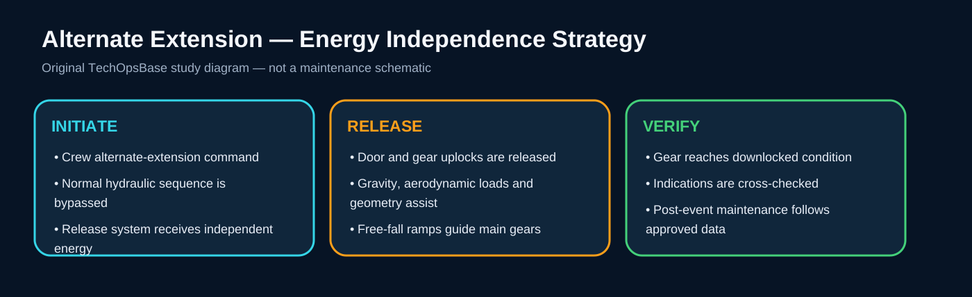
Alternate extension exists so that loss of the normal powered sequence does not automatically prevent landing-gear deployment. The alternate system releases the required uplocks using an independent method, after which gravity, airflow and landing-gear geometry help the gears move to the downlocked position.
Alternate extension is not simply normal extension at lower pressure. Door behavior, reset requirements, available indications and post-event maintenance can differ. The technician must treat it as a separate configuration and follow approved restoration data.

5. Wheels and braking
The wheel and brake system converts aircraft kinetic energy into heat while maintaining directional control. The normal braking system interprets pedal or autobrake demand and uses wheel-speed feedback for anti-skid control. Alternate and accumulator-supported paths preserve braking after failures. Parking braking holds the aircraft using stored hydraulic energy and commanded valves.
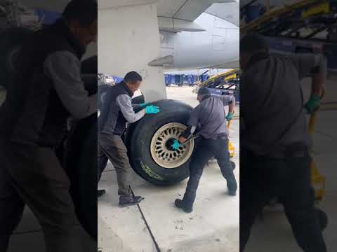
Tire pressure, brake temperature, brake wear, wheel condition and cooling state are maintenance concerns because stored energy and heat can remain hazardous long after movement stops.

6. Nose-wheel steering
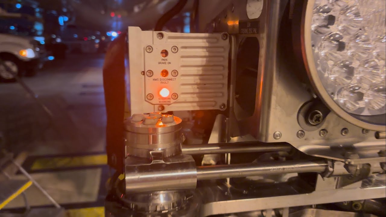
Nose-wheel steering combines pilot or system commands, speed-related limits, hydraulic actuation and closed-loop angle feedback. The steering system also interfaces with towing, centering, retraction and braking logic. A steering fault can therefore involve the command source, computer, hydraulic selection, actuator, feedback sensor, mechanical linkage or aircraft-state input.

7. Maintenance integration
ATA 32 troubleshooting begins by making the aircraft physically safe. Gear pins, door pins, wheel chocks, jacking state, hydraulic isolation, brake accumulator pressure, hot-brake zones and steering/towing configuration are not administrative details; they directly control injury and damage risk.
Once safe, use a structured sequence: establish the requested state, observe actual mechanical state, compare independent indications, review fault history, identify common power or data sources, then use current approved troubleshooting and test instructions.

Maintenance boundary
This lesson supports system understanding and maintenance reasoning. It deliberately excludes task steps, numerical limits, servicing quantities, torque values, dispatch decisions and configuration-specific instructions. Before touching the aircraft, confirm the current approved maintenance data, aircraft effectivity, safety procedures, tooling, personnel authorization and restoration requirements.
Review prompts
- What is the commanded function?
- Which computer or control channel accepts the command?
- Which energy source performs the movement or braking action?
- Which mechanical locks, valves or actuators must change state?
- Which sensors confirm that the commanded state was achieved?
- What independent or alternate path remains available?
- What hazards exist if maintenance personnel assume the indication alone proves the system is safe?