Educational familiarization only. This is original TechOpsBase learning content created from privately supplied legacy training and MSG-3 source material. It does not reproduce manufacturer pages, proprietary diagrams, task steps, numerical maintenance limits, dispatch criteria or controlled maintenance data. Current approved aircraft data, effectivity and operator procedures govern all aircraft work.
Resource profile
- Aircraft: Airbus A350 family
- ATA chapter: 38 — Water/Waste
- Resource: A350 ATA 38 Vacuum Toilet System Architecture
- Level: Intermediate-to-advanced
- Status: Draft pending technical review
Learning objectives
- Explain vacuum toilet flow.
- Identify toilet and control equipment.
- Describe flight-phase vacuum logic.
- Recognize autonomous/CIDS boundaries.
- Diagnose local and common flush faults.
1. Purpose and operational value
The vacuum toilet system moves waste from toilets to dedicated tanks by controlling rinse water, flush valves and available vacuum.
2. Architecture and system flow
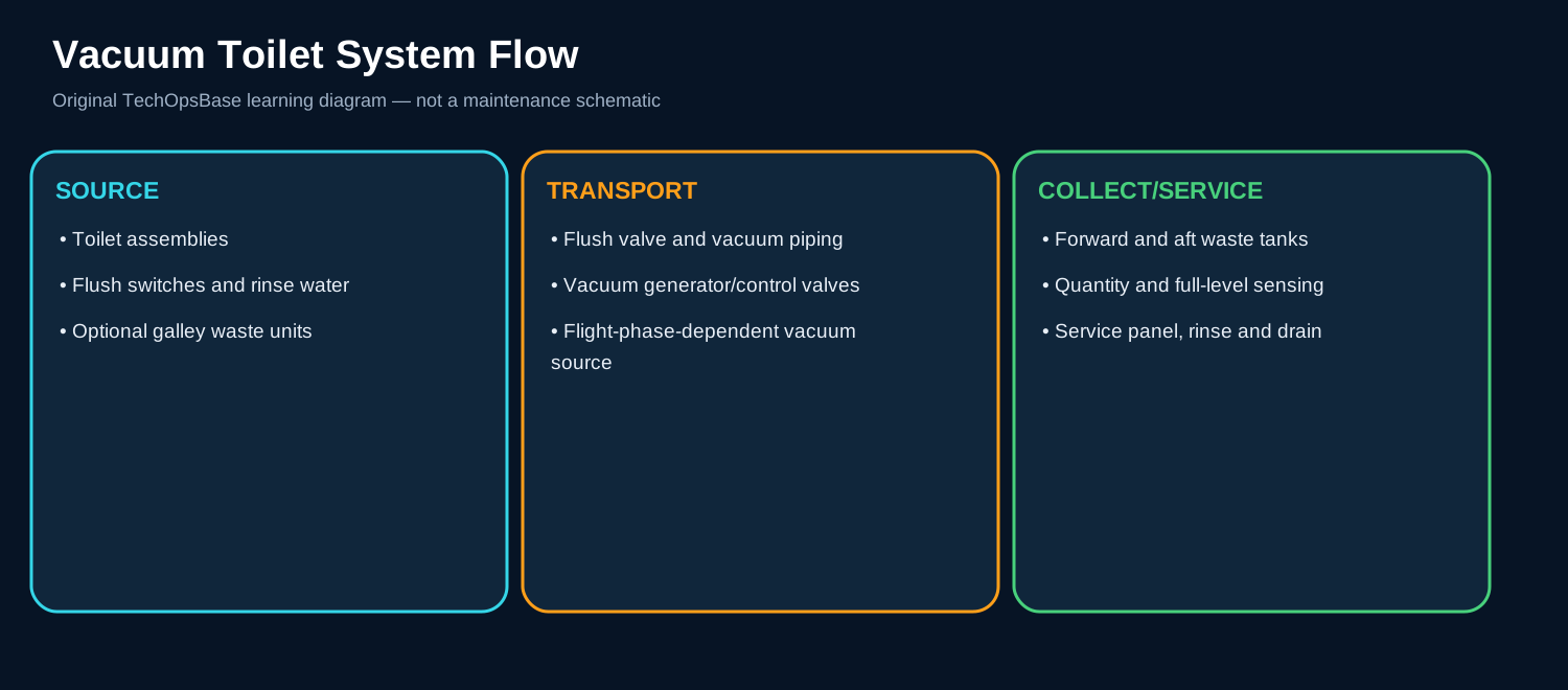
Toilets and optional galley waste units connect to forward or aft vacuum-waste subsystems.
A flush sequence coordinates user input, rinse water, flush-valve opening and available vacuum.
The waste system controls itself; CIDS transports indications, configuration and software data but does not perform the core vacuum control.
3. Major components and functions
Toilet assembly
Receives waste and controls the local flush path. The component must receive the correct input, perform its intended function and provide a valid output or status. A maintenance diagnosis must separate loss of power, loss of communication, incorrect configuration, blockage or leakage, contamination, mechanical degradation and an upstream or downstream interface failure. Useful evidence includes flush switch, controller, hall/position sensing, rinse and valve action. Command, feedback and physical effect must agree before hardware is condemned.
Flush switch
Requests a flush and provides user indication. The component must receive the correct input, perform its intended function and provide a valid output or status. A maintenance diagnosis must separate loss of power, loss of communication, incorrect configuration, blockage or leakage, contamination, mechanical degradation and an upstream or downstream interface failure. Useful evidence includes input, LED status and local wiring. Command, feedback and physical effect must agree before hardware is condemned.
Vacuum piping
Carries waste to the assigned tank. The component must receive the correct input, perform its intended function and provide a valid output or status. A maintenance diagnosis must separate loss of power, loss of communication, incorrect configuration, blockage or leakage, contamination, mechanical degradation and an upstream or downstream interface failure. Useful evidence includes blockage, leakage, attachment and subsystem routing. Command, feedback and physical effect must agree before hardware is condemned.
Vacuum source/control
Creates or controls differential pressure. The component must receive the correct input, perform its intended function and provide a valid output or status. A maintenance diagnosis must separate loss of power, loss of communication, incorrect configuration, blockage or leakage, contamination, mechanical degradation and an upstream or downstream interface failure. Useful evidence includes flight phase, vacuum generator/valve command and actual vacuum. Command, feedback and physical effect must agree before hardware is condemned.
System bus/controller
Coordinates local equipment and tank status. The component must receive the correct input, perform its intended function and provide a valid output or status. A maintenance diagnosis must separate loss of power, loss of communication, incorrect configuration, blockage or leakage, contamination, mechanical degradation and an upstream or downstream interface failure. Useful evidence includes power, CAN/bus, configuration and BITE. Command, feedback and physical effect must agree before hardware is condemned.
4. Normal operating sequence
1. Request
User activates the flush switch.
2. Validate
Controller checks phase, tank and system availability.
3. Rinse/open
Rinse water and flush valve operate in sequence.
4. Transport
Differential pressure moves waste to the tank.
5. Close/indicate
Valve closes and status/fault is recorded.
5. Control, monitoring and protection
A flush switch indication does not prove valve movement or vacuum transport.
One toilet can fail while the autonomous subsystem and CIDS indication remain healthy.
6. Failure modes and maintenance reasoning
- One toilet no flush: Local switch, controller, valve, rinse or branch blockage.
- Several toilets same side: Common bus, vacuum source or tank condition.
- All toilets unavailable: Power, common control, both subsystems or aircraft-state input.
- Flush starts but waste remains: Valve, vacuum or piping restriction.
- Repeated nuisance fault: Position sensor, contamination, wiring or configuration.
7. Interfaces with other aircraft systems
- Potable-water rinse supply.
- CIDS/FAP indication.
- ATA 24 power.
- Aircraft flight-phase/air-ground data.
- Waste tank and servicing system.
8. Practical maintenance scenarios
Switch LED changes but no flush
Trace local controller/valve/vacuum, not only the switch.
Only forward toilets affected
Use subsystem routing and common vacuum/tank evidence.
Flush works on ground but not flight
Review flight-phase logic and vacuum source state.
9. Technician takeaways
- The system is autonomous from CIDS control.
- Local and common faults have different patterns.
- Rinse and vacuum are separate requirements.
- Preserve tank/phase status.
Maintenance boundary
This resource explains architecture, operation, indications and system-level troubleshooting. It intentionally excludes removal/installation instructions, wiring-pin checks, maintenance limits, software part numbers, servicing quantities, inspection intervals and release-to-service criteria.
Review prompts
- What is the required system function?
- Which component commands, processes or physically performs it?
- Which power, fluid, pneumatic or data path is required?
- What command proves the function was requested?
- What feedback or physical effect proves correct operation?
- Which adjacent ATA system can create the same symptom?
- What evidence should be preserved before reset, draining, servicing or software action?
- What hygiene, electrical, pressure, network or safety boundary applies?