Educational familiarization only. This original TechOpsBase resource explains system purpose, architecture and maintenance reasoning. It does not reproduce Airbus pages, diagrams, task instructions or controlled maintenance data. Actual aircraft work requires current approved data, correct effectivity, operator procedures, authorization and supervision.
Resource profile
- Aircraft: Airbus A350 family
- ATA chapter: 27 - Flight Controls
- Audience: Students, junior technicians and working professionals
- Level: Intermediate familiarization
- Source basis: Privately supplied 2013-2014 manufacturer training and MSG-3 material
- Technical status: Draft pending technical review
Learning objectives
- Describe pedal, trim and yaw-law inputs.
- Explain rudder actuation and backup.
- Relate rudder travel to aircraft condition.
- Apply safe maintenance reasoning.
1. Pilot and automatic inputs
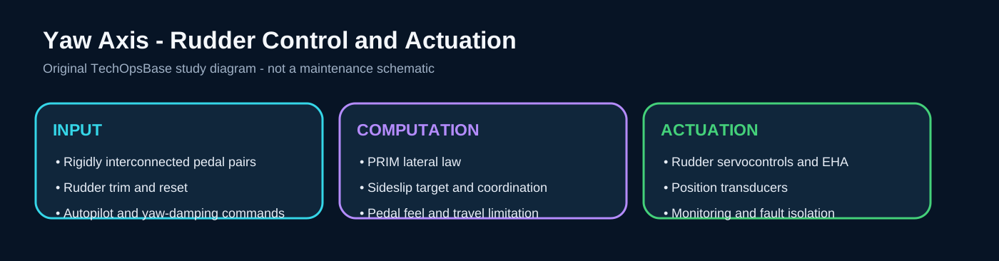
Captain and first-officer pedals are mechanically interconnected so either pilot commands the same pedal system. Position transducers send pedal demand to the flight-control computers. Rudder trim and reset controls modify the neutral command. Automatic functions add yaw damping, turn coordination, engine-failure compensation and sideslip targets.
Maintenance questions to ask
- What is the commanded condition and what independent evidence confirms it?
- Which computer, sensor, hydraulic and electrical channels are required in this configuration?
- Is the failure crew-evident, maintenance-evident or hidden until a dedicated test?
- Which current approved document and effectivity control the next action?
2. Feel and travel management
The pedal feel and trim unit gives artificial force and trim movement. Rudder authority is scheduled with aircraft condition so low-speed control remains strong while high-speed structural loads are limited. A disagreement between pedal demand, feel-system position and computer acquisition can lead to warnings or reduced capability.
Maintenance questions to ask
- What is the commanded condition and what independent evidence confirms it?
- Which computer, sensor, hydraulic and electrical channels are required in this configuration?
- Is the failure crew-evident, maintenance-evident or hidden until a dedicated test?
- Which current approved document and effectivity control the next action?
3. Rudder actuation
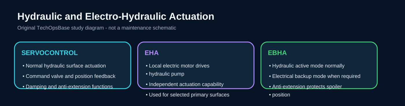
The rudder uses distributed hydraulic actuation and electro-hydrostatic backup. Active actuators position the surface while inactive channels provide the required damping or restraint. Surface-position transducers allow computers to compare the commanded and actual rudder angle.

Maintenance questions to ask
- What is the commanded condition and what independent evidence confirms it?
- Which computer, sensor, hydraulic and electrical channels are required in this configuration?
- Is the failure crew-evident, maintenance-evident or hidden until a dedicated test?
- Which current approved document and effectivity control the next action?
4. Monitoring and isolation
The computers detect command/feedback disagreement, actuator disconnection, electrical or hydraulic unavailability and position-data faults. One failure may be crew-evident; another may only remove redundancy and remain hidden until a test or second failure. This distinction is central to the maintenance program.

Maintenance questions to ask
- What is the commanded condition and what independent evidence confirms it?
- Which computer, sensor, hydraulic and electrical channels are required in this configuration?
- Is the failure crew-evident, maintenance-evident or hidden until a dedicated test?
- Which current approved document and effectivity control the next action?
5. Failure effects
Loss of one control or actuation channel can leave yaw control available through remaining channels, but dispatch or automatic-flight capability may be reduced. An uncontrolled surface or incorrect trim condition can have larger consequences and is protected by monitoring, independent channels and physical restraint.
Maintenance questions to ask
- What is the commanded condition and what independent evidence confirms it?
- Which computer, sensor, hydraulic and electrical channels are required in this configuration?
- Is the failure crew-evident, maintenance-evident or hidden until a dedicated test?
- Which current approved document and effectivity control the next action?
6. Maintenance practice
Before moving the rudder, confirm personnel and equipment are clear. Check pedal and rudder position data, trim reset, hydraulic source, actuator mode and computer status. Use approved tests for hidden backup or damping functions. Do not use free movement as proof that all protection channels are serviceable.
Maintenance questions to ask
- What is the commanded condition and what independent evidence confirms it?
- Which computer, sensor, hydraulic and electrical channels are required in this configuration?
- Is the failure crew-evident, maintenance-evident or hidden until a dedicated test?
- Which current approved document and effectivity control the next action?
Integrated review
Use the input ? computation ? power ? actuation ? feedback ? indication model. A correct diagnosis must explain both the physical symptom and every associated message. Avoid replacing a computer merely because it generated the warning; it may be reporting loss of an external input, power source or actuator response.
Key takeaways
- Describe pedal, trim and yaw-law inputs.
- Explain rudder actuation and backup.
- Relate rudder travel to aircraft condition.
- Apply safe maintenance reasoning.
Current approved maintenance data always controls aircraft work.