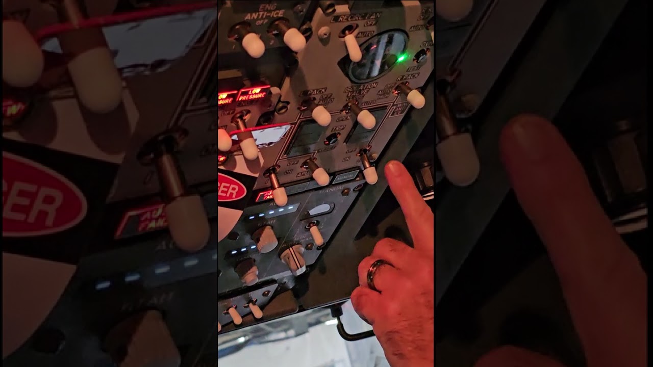
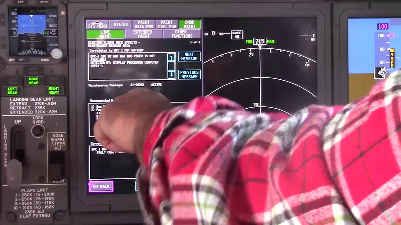
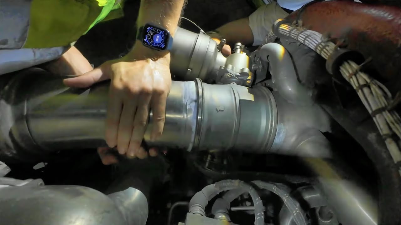
Educational familiarization only. This TechOpsBase resource is an original learning transformation grounded in a privately supplied B737 MAX ATA 36 source. It does not reproduce manufacturer task steps, limits, figures or controlled maintenance instructions. Current approved data and aircraft effectivity control real work.
What this resource teaches
Build the complete source-to-user map before learning individual bleed valves.
Three practical source categories
The chapter explicitly supports pneumatic pressure from an external ground source, the APU, or one/both engines. These are alternative upstream energy sources feeding a common distribution concept.
The users explain why ATA 36 matters
The source lists air-conditioning packs, engine cowl anti-ice, wing thermal anti-ice, engine starting, hydraulic-reservoir pressurization and water-tank pressurization as pneumatic users. A single upstream issue can therefore create symptoms across several ATA chapters.
Source pressure and user performance are different layers
A source may produce pressure but a manifold/valve path can prevent a user from receiving it. A user may also be disabled or faulty even with normal manifold pressure.
Cross-ATA reasoning
ATA 21 cooling, ATA 30 anti-ice, ATA 29 reservoir pressurization and ATA 38 water pressurization all provide clues about the ATA 36 network.
Start every symptom with the map
Ask: which source should be active, what manifold/path should be open, and which user is affected? If multiple users share the same weak side, move the hypothesis upstream.
Put this topic into the wider system
Shared users make common-mode clues powerful
A pneumatic manifold supports several systems. When packs, anti-ice, starting or pressurization-related users on the same side show correlated weakness, a shared source/manifold hypothesis becomes stronger. When only one user is affected with normal manifold evidence, reason farther downstream.
Valve position needs context
IPCV, HPSOV, PRSOV and isolation-valve positions depend on source condition, controller logic and configuration. A position that is correct in one state can be wrong in another, so never judge valve health from a memorized “normal” position without context.
Deeper system reasoning
The isolation valve changes the network topology
The left and right manifold halves can be connected or separated through the isolation path. That means the same source can potentially support different users depending on configuration, and a change in isolation state can be used as evidence to distinguish source-side from downstream problems. The supplied material also shows that IASC logic can change high-pressure valve behavior with engine/isolation configuration, reinforcing that valve state is a computed system response, not an independent truth.
Pressure, temperature and indication should be logged separately
Pneumatic faults can involve insufficient pressure, excessive pressure, overtemperature, leakage or an indication/control issue. The chapter provides duct-pressure indication and maintenance/BITE functions along with health/leak checks. A technician should therefore record actual source configuration, duct-pressure evidence, affected users and protection/status messages as separate streams. The approved IFIM/AMM then determines the test path; TechOpsBase only teaches how to organize the evidence.
Technician evidence matrix
Record active source, engine/APU/ground configuration, isolation/manifold state, duct-pressure evidence, affected users on each side and any protection/BITE indication.
Before using a maintenance message as a conclusion, note what independent evidence agrees with it and what evidence does not. If an alternate source, channel or display changes the symptom, record that explicitly because it can separate a common path from a source-specific path. Preserve configuration and event conditions in the handover so the next technician does not have to rebuild the diagnostic context from memory.
Evidence-first study method
For any system complaint, separate source/input, control logic, physical response, sensing/indication and consumer/result. When two layers disagree, that disagreement is useful evidence. Do not turn that evidence into a maintenance action until the applicable approved fault-isolation or maintenance data is open.
Approved-data boundary
Educational system explanation only. Do not use this page to perform maintenance, operate aircraft systems, isolate components or determine dispatch status. Current approved maintenance data, aircraft effectivity and operator procedures control real aircraft work.