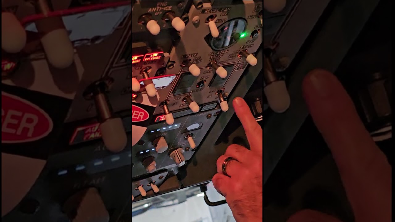
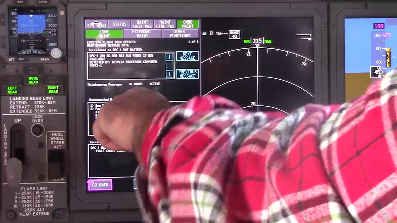
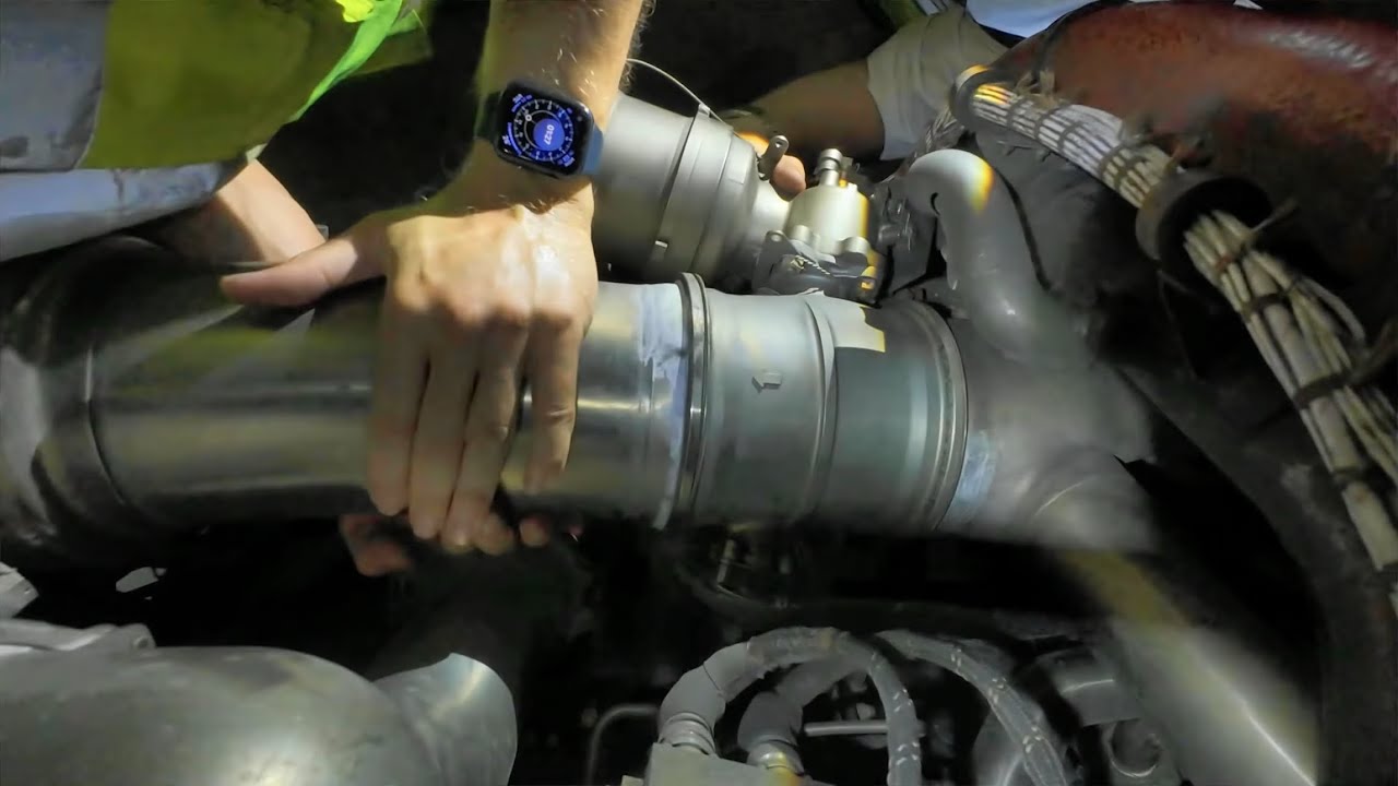
Educational familiarization only. This TechOpsBase resource is an original learning transformation grounded in a privately supplied B737 MAX ATA 36 source. It does not reproduce manufacturer task steps, limits, figures or controlled maintenance instructions. Current approved data and aircraft effectivity control real work.
What this resource teaches
Use pressure, valve state, controller logic and user behavior as separate evidence streams.
Duct pressure is a system-level measurement
The chapter includes duct-pressure transducers and a dual-duct pressure indicator. This gives a high-level view of manifold condition, not a direct diagnosis of every upstream valve.
IASC adds control intelligence
The Integrated Air Systems Controller participates in bleed control and built-in tests. Controller logic uses multiple conditions, so the commanded state of a valve can be configuration-dependent.
Protection has multiple triggers
The source contains overtemperature, overpressure and reverse-flow shutdown context as well as a protection-gate test. These protections explain why a system can close a valve even when the mechanical valve itself is capable of opening.
Leak evidence spans the physical path
Engine bleed leak checks cover precooler ducts, major valves, check valves and sense lines. A leak can therefore influence pressure and control evidence before it becomes visually obvious.
Troubleshooting framework
Source condition ? controller inputs/logic ? valve response ? manifold pressure ? user response. When BITE reports a failure, use it to choose approved fault-isolation data rather than treating the message as a replacement instruction.
Put this topic into the wider system
Shared users make common-mode clues powerful
A pneumatic manifold supports several systems. When packs, anti-ice, starting or pressurization-related users on the same side show correlated weakness, a shared source/manifold hypothesis becomes stronger. When only one user is affected with normal manifold evidence, reason farther downstream.
Valve position needs context
IPCV, HPSOV, PRSOV and isolation-valve positions depend on source condition, controller logic and configuration. A position that is correct in one state can be wrong in another, so never judge valve health from a memorized “normal” position without context.
Deeper system reasoning
The isolation valve changes the network topology
The left and right manifold halves can be connected or separated through the isolation path. That means the same source can potentially support different users depending on configuration, and a change in isolation state can be used as evidence to distinguish source-side from downstream problems. The supplied material also shows that IASC logic can change high-pressure valve behavior with engine/isolation configuration, reinforcing that valve state is a computed system response, not an independent truth.
Technician evidence matrix
Record active source, engine/APU/ground configuration, isolation/manifold state, duct-pressure evidence, affected users on each side and any protection/BITE indication.
Before using a maintenance message as a conclusion, note what independent evidence agrees with it and what evidence does not. If an alternate source, channel or display changes the symptom, record that explicitly because it can separate a common path from a source-specific path. Preserve configuration and event conditions in the handover so the next technician does not have to rebuild the diagnostic context from memory.
Evidence-first study method
For any system complaint, separate source/input, control logic, physical response, sensing/indication and consumer/result. When two layers disagree, that disagreement is useful evidence. Do not turn that evidence into a maintenance action until the applicable approved fault-isolation or maintenance data is open.
Approved-data boundary
Educational system explanation only. Do not use this page to perform maintenance, operate aircraft systems, isolate components or determine dispatch status. Current approved maintenance data, aircraft effectivity and operator procedures control real aircraft work.