Educational familiarization only. This TechOpsBase resource is an original learning transformation grounded in a privately supplied B737 MAX ATA 24 source. It does not reproduce manufacturer task steps, limits, figures or controlled maintenance instructions. Current approved data and aircraft effectivity control real work.
What this resource teaches
Learn how multiple sources feed AC buses and why transfer/contact logic is more useful than memorizing switch positions.
Buses create organized distribution
Aircraft electrical loads are grouped onto buses so that source changes, protection and load management can be controlled. A bus fault therefore affects a set of loads with a meaningful common point.
Transfer logic creates resilience
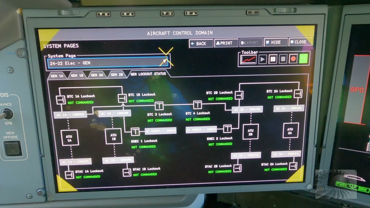
The chapter contains bus transfer and bus-power-control functions. A useful mental model is that the system tries to connect an acceptable source to the required bus while preventing unsafe source combinations.
Source priority is contextual
External power, APU power and engine-driven generation can all appear in the same architecture. Instead of memorizing a universal priority rule from a study page, learn to identify which source is selected, which source is available and which contact path should connect it in the current configuration.
Common-mode clues
Several unrelated loads disappearing together points toward a shared bus or upstream source. One load disappearing while the bus remains healthy points farther downstream. This simple grouping logic is powerful and does not require procedural steps.
Maintenance-data boundary
Actual contactor logic, exact voltage/frequency limits and electrical isolation procedures belong to current approved data and the aircraft wiring/maintenance manuals.
Put this topic into the wider system
Control and protection can create an intentional disconnect
A physically capable generator or external source may be rejected when control/protection logic decides that the source is not acceptable. Therefore “source present but bus dead” can be a control/connection problem rather than a failed generator.
Generated, converted and stored energy are different
IDG/APU/external sources provide or deliver AC energy, TRUs convert AC to DC, and the battery stores energy. Keeping those roles distinct helps explain why an apparently DC-only symptom can have an upstream AC cause and why standby power can depend on conversion between domains.
Deeper system reasoning
Build the AC source hierarchy first
The chapter contains engine-driven IDGs, APU generator power, external power, generator control and the main AC distribution path. The useful mental model is source ? qualification/control ? breaker/contactor connection ? bus ? load. A generator that can physically produce power may still be intentionally disconnected by protection or control logic. Conversely, a healthy bus supplied from one source but not another is strong evidence that the common downstream distribution may be healthy and the source-specific path deserves attention.
Separate generation, conversion and storage
ATA 24 contains AC generation, transformer-rectifier units, batteries/chargers and standby power. Those are different energy roles. IDG/APU/external sources provide AC power; TRUs convert AC to DC; batteries store DC energy; standby architecture selects or converts sources so essential loads can remain powered. This separation matters because a DC symptom can originate in AC supply or conversion, while a standby complaint can involve battery condition, static-inverter/SPCU logic, or the normal source path rather than one simple “battery problem.”
Technician evidence matrix
Record active/available sources, which bus/load group is affected, whether an alternate source changes the symptom, conversion/battery state and whether the indication agrees with actual load operation.
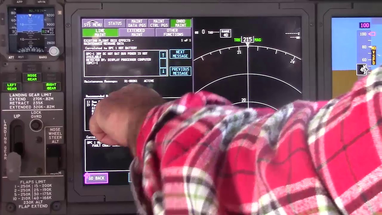
Before using a maintenance message as a conclusion, note what independent evidence agrees with it and what evidence does not. If an alternate source, channel or display changes the symptom, record that explicitly because it can separate a common path from a source-specific path. Preserve configuration and event conditions in the handover so the next technician does not have to rebuild the diagnostic context from memory.
Evidence-first study method
For any system complaint, separate source/input, control logic, physical response, sensing/indication and consumer/result. When two layers disagree, that disagreement is useful evidence. Do not turn that evidence into a maintenance action until the applicable approved fault-isolation or maintenance data is open.
Approved-data boundary
Educational system explanation only. Do not use this page to perform maintenance, operate aircraft systems, isolate components or determine dispatch status. Current approved maintenance data, aircraft effectivity and operator procedures control real aircraft work.