Educational familiarization only. This original TechOpsBase lesson was developed from privately supplied legacy A350 training and MSG-3 material. It does not reproduce manufacturer pages, proprietary diagrams, maintenance task steps, numerical maintenance limits, dispatch criteria or controlled maintenance data. Current approved aircraft data, correct effectivity, operator procedures and authorization govern all aircraft work.
Resource profile
- Aircraft: Airbus A350 family
- ATA chapter: 36 - Pneumatic
- Resource: A350 ATA 36 Pneumatic System Maintenance, Tooling and Access
- Audience: Enthusiasts, students, junior technicians and professionals
- Level: Intermediate-to-advanced
- Status: Draft pending technical review
Learning objectives
- Explain the subsystem architecture and purpose.
- Identify the major components and interfaces.
- Trace command, pneumatic flow and feedback.
- Recognize protection and failure patterns.
- Apply evidence-based maintenance reasoning.
1. Purpose and operational value
ATA 36 maintenance combines hot/high-pressure safety, specialized functional testing, difficult access and careful handling of heavy duct/valve components.
2. Architecture and system flow
A dedicated bleed test set can exercise and evaluate on-wing pneumatic components under approved procedures.
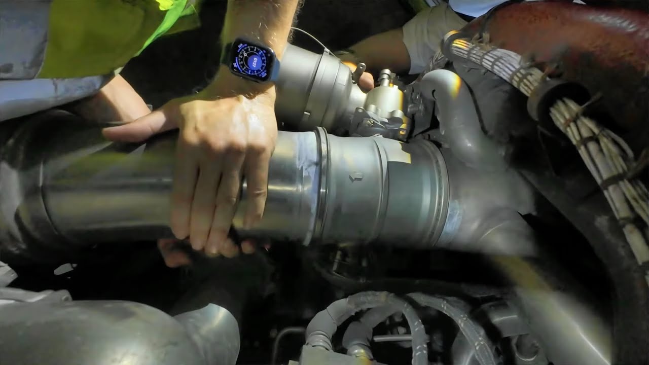
Precooler, regulating valves and the engine T-duct require controlled support and handling because of location, mass and installation loads.
Selected valves have approved manual deactivation/locking features with local position indication.
CMS leak-location data directs maintenance to the correct TSM zone and access-panel reference.
3. Major components and functions
Bleed test set
Provides controlled test inputs and measurements for on-wing component evaluation. It must receive the correct pneumatic or electronic input, perform the expected function and return a believable output or status. A fault can result from electrical power, data communication, a blocked or leaking pressure/sense line, pneumatic contamination, mechanical friction, incorrect configuration, a failed sensor or an upstream/downstream system request. Useful evidence includes correct configuration, connections, measured response and approved limits. A maintenance conclusion is strongest when command, feedback and physical pneumatic effect agree.
Lifting/support equipment
Carries heavy valves, precooler or duct components safely. It must receive the correct pneumatic or electronic input, perform the expected function and return a believable output or status. A fault can result from electrical power, data communication, a blocked or leaking pressure/sense line, pneumatic contamination, mechanical friction, incorrect configuration, a failed sensor or an upstream/downstream system request. Useful evidence includes rated equipment, attachment points, balance and access clearance. A maintenance conclusion is strongest when command, feedback and physical pneumatic effect agree.
Manual locking devices
Secure selected valves in an approved deactivated state. It must receive the correct pneumatic or electronic input, perform the expected function and return a believable output or status. A fault can result from electrical power, data communication, a blocked or leaking pressure/sense line, pneumatic contamination, mechanical friction, incorrect configuration, a failed sensor or an upstream/downstream system request. Useful evidence includes mechanical position, locking security and cockpit/maintenance configuration. A maintenance conclusion is strongest when command, feedback and physical pneumatic effect agree.
Access panels
Provide entry to valves, ducts and detection zones. It must receive the correct pneumatic or electronic input, perform the expected function and return a believable output or status. A fault can result from electrical power, data communication, a blocked or leaking pressure/sense line, pneumatic contamination, mechanical friction, incorrect configuration, a failed sensor or an upstream/downstream system request. Useful evidence includes correct panel reference, safe opening and restoration. A maintenance conclusion is strongest when command, feedback and physical pneumatic effect agree.
CMS/TSM localization
Converts stored fault location into a focused inspection area. It must receive the correct pneumatic or electronic input, perform the expected function and return a believable output or status. A fault can result from electrical power, data communication, a blocked or leaking pressure/sense line, pneumatic contamination, mechanical friction, incorrect configuration, a failed sensor or an upstream/downstream system request. Useful evidence includes message code, zone table, access reference and related fault history. A maintenance conclusion is strongest when command, feedback and physical pneumatic effect agree.
4. Normal operating sequence
1. Prepare
Depressurize, cool, isolate electrical/pneumatic sources and establish access.
2. Preserve
Save fault data and original valve/source configuration.
3. Test/inspect
Use approved equipment and targeted access.
4. Handle/replace
Support components without loading adjacent ducts or fittings.
5. Restore
Remove deactivation, verify configuration, leak tightness, regulation and protection.
5. Control, monitoring and protection
A manual lock or override changes the aircraft configuration and must be controlled, recorded and removed according to approved data.
A component can pass a basic movement test but fail under real pressure, temperature or flow demand.
After a confirmed leak, inspect surrounding structure, insulation, wiring and detection elements as well as the failed pneumatic part.
6. Failure modes and maintenance reasoning
- Test result inconsistent: Wrong setup, source condition, tool connection or intermittent component.
- Replacement difficult/alignment poor: Support/load issue or adjacent duct distortion.
- Leak location unclear: Incomplete fault data, wrong zone mapping or multiple events.
- Manual deactivation indication wrong: Locking position versus electrical feedback mismatch.
- Repeat fault after replacement: Installation, sense line, control channel or upstream cause.
7. Interfaces with other systems
- AMM/TSM/CMS.
- Ground support equipment.
- Electrical and pneumatic isolation.
- Aircraft structure and access.
- BAS/BAM/OHDS tests.
8. Practical maintenance scenarios
Valve replacement followed by regulation fault
Check remote-servo/sense-line connections, installation alignment and configuration.
CMS points to a narrow leak zone
Use that location to minimize unnecessary access opening.
Component moves with test set but aircraft fault remains
Recreate the real source, temperature and control conditions.
9. Technician takeaways
- Tool setup is part of the test result.
- Heavy components require planned support.
- Manual deactivation is a controlled aircraft configuration.
- Verify the full system, not only the replaced component.
Maintenance boundary
This resource explains system architecture, normal operation, indication and maintenance reasoning. It intentionally excludes removal/installation procedures, wiring-pin checks, valve rigging, leak-test limits, servicing limits, maintenance intervals, software part numbers, dispatch decisions and release-to-service criteria.
Review prompts
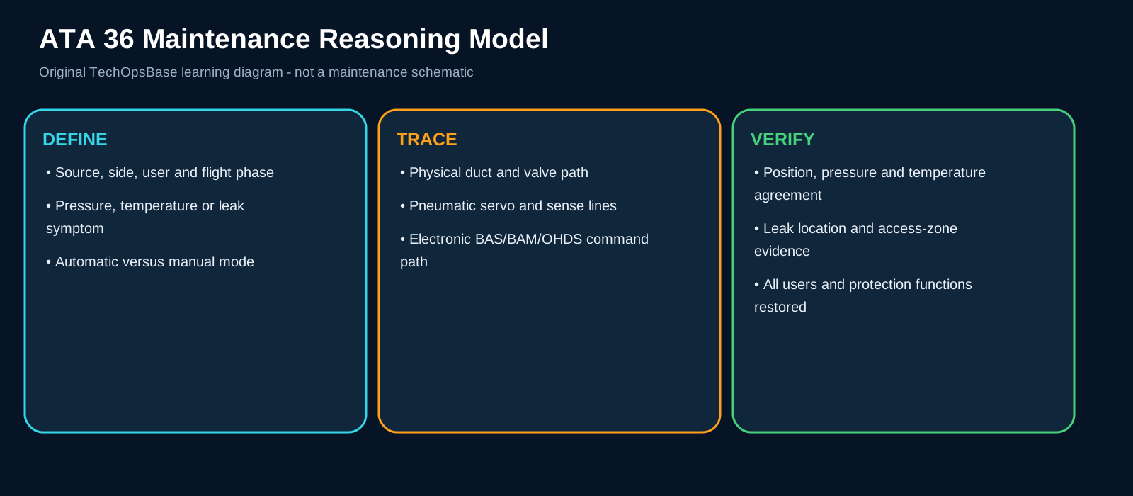
- Which pneumatic source should be available in this configuration?
- Which valve or controller establishes the expected flow path?
- Which pressure, temperature or position feedback proves the command was achieved?
- Is the symptom local to one side, one source, one user or the complete manifold?
- Could a user-system demand or isolation command explain the observed state?
- Is the fault in the physical air path, the pneumatic control path or the electronic command path?
- What evidence must be preserved before reset, source change or manual override?
- What hot-air, pressure, moving-equipment and structural-protection boundary applies?