Educational familiarization only. This original TechOpsBase lesson was developed from privately supplied legacy A350 training and MSG-3 material. It does not reproduce manufacturer pages, proprietary diagrams, maintenance task steps, numerical maintenance limits, dispatch criteria or controlled maintenance data. Current approved aircraft data, correct effectivity, operator procedures and authorization govern all aircraft work.
Resource profile
- Aircraft: Airbus A350 family
- ATA chapter: 36 - Pneumatic
- Resource: A350 ATA 36 Engine Bleed Operation, Protection and Indication
- Audience: Enthusiasts, students, junior technicians and professionals
- Level: Intermediate-to-advanced
- Status: Draft pending technical review
Learning objectives
- Explain the subsystem architecture and purpose.
- Identify the major components and interfaces.
- Trace command, pneumatic flow and feedback.
- Recognize protection and failure patterns.
- Apply evidence-based maintenance reasoning.
1. Purpose and operational value
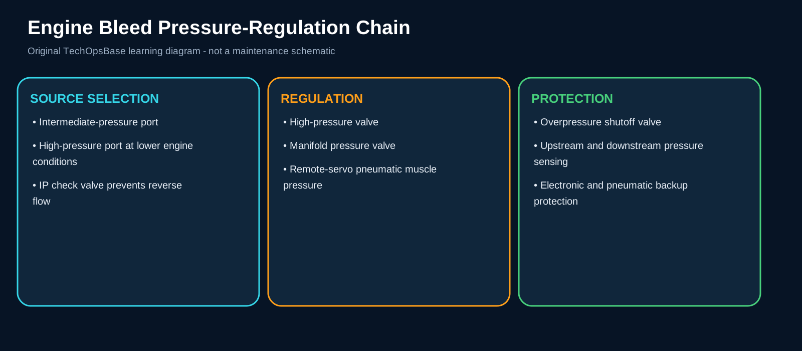
EBAS operation coordinates engine condition, source demand, regulating valves and independent protection while presenting usable status to the crew.
2. Architecture and system flow
Electronic mode provides normal regulation through BAS and the remote-servo system.
Pneumatic mode provides a backup regulating behavior after selected electronic/control failures.
Both BAS and BAM monitor abnormal pressure and temperature through independent data paths.
Cockpit indication combines measured pressure, temperature and inferred valve/source state.
3. Major components and functions
Electronic regulation mode
Provides precise commanded control. It must receive the correct pneumatic or electronic input, perform the expected function and return a believable output or status. A fault can result from electrical power, data communication, a blocked or leaking pressure/sense line, pneumatic contamination, mechanical friction, incorrect configuration, a failed sensor or an upstream/downstream system request. Useful evidence includes BAS state, CRDC output and servo response. A maintenance conclusion is strongest when command, feedback and physical pneumatic effect agree.
Pneumatic backup mode
Maintains a fallback regulating condition. It must receive the correct pneumatic or electronic input, perform the expected function and return a believable output or status. A fault can result from electrical power, data communication, a blocked or leaking pressure/sense line, pneumatic contamination, mechanical friction, incorrect configuration, a failed sensor or an upstream/downstream system request. Useful evidence includes de-energized torque motors, valve behavior and remaining pressure. A maintenance conclusion is strongest when command, feedback and physical pneumatic effect agree.
Protection chain
Closes regulating and protective valves for abnormal conditions. It must receive the correct pneumatic or electronic input, perform the expected function and return a believable output or status. A fault can result from electrical power, data communication, a blocked or leaking pressure/sense line, pneumatic contamination, mechanical friction, incorrect configuration, a failed sensor or an upstream/downstream system request. Useful evidence includes BAS/BAM requests, valve response and pressure/temperature decay. A maintenance conclusion is strongest when command, feedback and physical pneumatic effect agree.
Pressure indication
Shows manifold condition from the designated monitoring channel. It must receive the correct pneumatic or electronic input, perform the expected function and return a believable output or status. A fault can result from electrical power, data communication, a blocked or leaking pressure/sense line, pneumatic contamination, mechanical friction, incorrect configuration, a failed sensor or an upstream/downstream system request. Useful evidence includes sensor availability and plausibility. A maintenance conclusion is strongest when command, feedback and physical pneumatic effect agree.
Valve/source indication
Shows interpreted source and valve state. It must receive the correct pneumatic or electronic input, perform the expected function and return a believable output or status. A fault can result from electrical power, data communication, a blocked or leaking pressure/sense line, pneumatic contamination, mechanical friction, incorrect configuration, a failed sensor or an upstream/downstream system request. Useful evidence includes feedback, pressure and display logic. A maintenance conclusion is strongest when command, feedback and physical pneumatic effect agree.
4. Normal operating sequence
1. Engine start
Bleed valves remain in the required safe state during the start sequence.
2. Engine running
Valves transition to normal pressure and temperature regulation.
3. APU priority
Engine bleed sides isolate when APU source is selected.
4. Leak/overheat response
Affected engine bleed valves close to remove hot-air supply.
5. Manual OFF/fire isolation
Cockpit isolation commands drive the engine bleed valves closed.
5. Control, monitoring and protection
One invalid display sensor can remove a pressure value while independent protection remains available.
A valve can be commanded closed for a legitimate external isolation request, so valve replacement is not the first conclusion.
After a protective event, restoring the pushbutton state does not prove the initiating pressure, temperature or leak problem is gone.
6. Failure modes and maintenance reasoning
- Pressure crosses/invalid: Display sensor/channel rather than immediate source loss.
- OFF/FAULT state: Manual selection, protection, valve failure or indication logic.
- Pneumatic-mode operation: Electronic-control fault with remaining mechanical regulation.
- Source closes unexpectedly: Leak, overpressure, overtemperature or user isolation.
- Incorrect valve status: Feedback, sensor, wiring or display interpretation.
7. Interfaces with other systems
- Engine interface data.
- APU source-priority logic.
- OHDS isolation requests.
- FWS/CDS.
- CMS/condition monitoring.
8. Practical maintenance scenarios
Displayed pressure unavailable but packs operate
Check the indication channel before assuming no bleed source.
Source closes during high demand
Preserve pressure/temperature and protection records.
Valve remains closed after reset
Identify the continuing isolation request or mechanical fault.
9. Technician takeaways
- Indication is interpreted system data, not direct visual proof.
- Protection commands can originate outside EBAS.
- Pneumatic backup must not be confused with full normal operation.
- Record the first protective event.
Maintenance boundary
This resource explains system architecture, normal operation, indication and maintenance reasoning. It intentionally excludes removal/installation procedures, wiring-pin checks, valve rigging, leak-test limits, servicing limits, maintenance intervals, software part numbers, dispatch decisions and release-to-service criteria.
Review prompts
- Which pneumatic source should be available in this configuration?
- Which valve or controller establishes the expected flow path?
- Which pressure, temperature or position feedback proves the command was achieved?
- Is the symptom local to one side, one source, one user or the complete manifold?
- Could a user-system demand or isolation command explain the observed state?
- Is the fault in the physical air path, the pneumatic control path or the electronic command path?
- What evidence must be preserved before reset, source change or manual override?
- What hot-air, pressure, moving-equipment and structural-protection boundary applies?