Educational familiarization only. This TechOpsBase resource is an original learning transformation grounded in a privately supplied B737 MAX ATA 31 source. It does not reproduce manufacturer task steps, limits, figures or controlled maintenance instructions. Current approved data and aircraft effectivity control real work.
What this resource teaches
Understand how display-processing computers create graphics for four display units and how control panels select what the crew and maintenance staff see.
DPCs generate the display content
The source states that loadable software parts in the Display Processing Computers (DPCs) supply graphics to the display units. This makes the DPC a processing/software layer and the DU a display/output layer.
Four display units form the visible interface
The chapter identifies four MAX display units in the forward instrument panel. A visible display problem can therefore originate in a DU, processing source, input/interface, configuration/software or power/cooling path.
Control panels change presentation
EFIS/display controls, the multifunction panel and instrument switching functions influence what is selected and where it appears. Selection is not the same as source validity.
Power and cooling are dependencies
The system tests require powered, serviceable DUs/DPCs and explicitly call out cooling air. That is a useful cross-link back to ATA 21 equipment cooling and ATA 24 electrical power.
Reasoning model
Data/input ? DPC processing/software ? display bus/interface ? DU ? selected presentation. Maintenance controls observe/test that chain.
Put this topic into the wider system
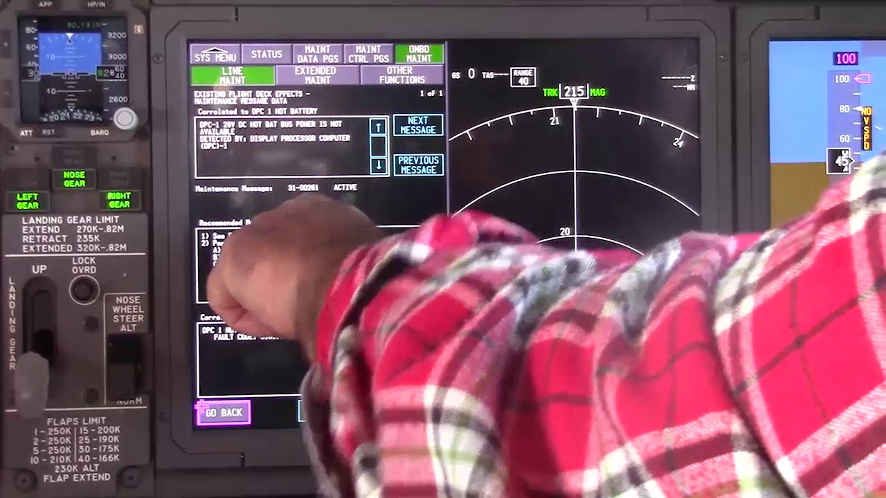
Maintenance pages preserve time context
Real-time data and stored snapshots answer different questions. A transient event may be gone by the time maintenance arrives, so preserved AUTO/MANUAL snapshots can be more valuable than a normal current reading. Always record the event timing and operating condition with the data.
Software/configuration is a real failure class
Modern display systems are software-configured. A CONFIG state, wrong loadable software or incompatible option can create a functional issue without a physically failed LRU. This is why configuration evidence should be checked before hardware assumptions become expensive.
Deeper system reasoning
ATA 31 connects maintenance across the airplane
The maintenance-data selection includes multiple ATA systems, so ATA 31 becomes an observation hub for aircraft maintenance rather than the owner of every message it displays. The chapter also references ATA 46/ONS for software/data functions and IFIM/WDM for approved diagnosis. Good reasoning therefore identifies the source ATA/LRU/interface first, then uses MDS information to narrow the approved troubleshooting path.
MDS is both presentation and maintenance infrastructure
The MAX Display System includes display processing computers, display units, control panels and loadable software. It presents operational information, but it also hosts maintenance functions. That dual role matters: a message shown on MDS may originate in another ATA system, while an MDS fault can itself affect how otherwise-good source data is presented. The first split is therefore source data versus display/processing/presentation.
Technician evidence matrix
Record which display/presentation is affected, whether source data is wrong elsewhere, DPC/DU/configuration status, REAL versus snapshot evidence and relevant maintenance messages.
Before using a maintenance message as a conclusion, note what independent evidence agrees with it and what evidence does not. If an alternate source, channel or display changes the symptom, record that explicitly because it can separate a common path from a source-specific path. Preserve configuration and event conditions in the handover so the next technician does not have to rebuild the diagnostic context from memory.
Evidence-first study method
For any system complaint, separate source/input, control logic, physical response, sensing/indication and consumer/result. When two layers disagree, that disagreement is useful evidence. Do not turn that evidence into a maintenance action until the applicable approved fault-isolation or maintenance data is open.
Approved-data boundary
Educational system explanation only. Do not use this page to perform maintenance, operate aircraft systems, isolate components or determine dispatch status. Current approved maintenance data, aircraft effectivity and operator procedures control real aircraft work.