Educational familiarization only. This original TechOpsBase lesson explains system architecture, operating logic and maintenance reasoning. It does not reproduce Airbus pages, illustrations, task steps, limits or controlled maintenance data. Current approved data, aircraft effectivity, operator procedures and authorization always control actual aircraft work.
Resource profile
- Aircraft: Airbus A350 family
- ATA: 21 — Air Conditioning
- Level: Intermediate to advanced familiarization
- Audience: Students, junior technicians and working professionals
- Technical status: Draft pending technical review
- Source treatment: Original educational content derived from privately supplied legacy training material; no source PDF is redistributed
Learning objectives
- Build a clear mental model of the complete system.
- Trace commands, airflow, heat transfer and feedback.
- Recognize normal, degraded and protective configurations.
- Separate source, control, mechanical and indication faults.
- Apply safe maintenance reasoning without replacing approved data.
1. Purpose of recirculation
Recirculation reduces pack workload while maintaining continuous cabin air movement. It is not used to eliminate fresh air. The architecture combines fresh conditioned air with filtered cabin return air.
Understanding this balance prevents the false assumption that weak cabin airflow must come from a pack.
2. Mixer-unit function
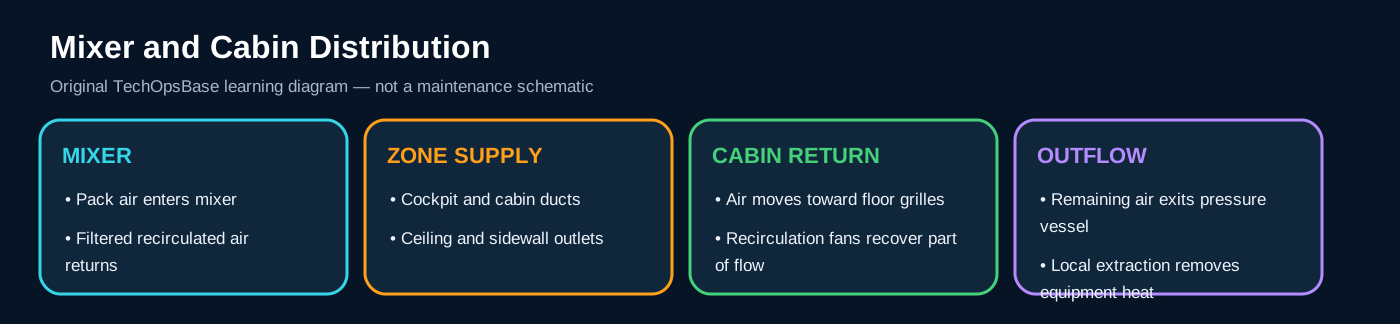
The mixer is the central blending and distribution point. It receives both pack outputs and the return flow from recirculation fans.
A mixer leak, internal obstruction or uneven inlet condition can affect several downstream zones even when pack outlet measurements appear normal.
3. Recirculation fans
Fans draw cabin air through return grilles and filters. Electrical status, rotational status and actual airflow are separate pieces of evidence.
A fan can run with low performance because of worn bearings, damaged blades, filter restriction, duct leakage or incorrect rotation after maintenance.
4. Filters and air quality
Filters trap particulates before air returns to the mixer. Their condition affects pressure drop, fan load and air quality.
Filter replacement is not only a comfort task. Incorrect installation, damaged seals or missed contamination can affect system performance.
5. Cabin supply zones
The distribution system serves cockpit and cabin areas through overhead and sidewall ducts. Zone architecture supports comfort but does not make every outlet independent.
A restriction upstream of one branch creates a local symptom; a mixer or pack problem usually affects a wider area.
6. Return-air and extraction path
Air moves from supply outlets through occupied spaces toward lower extraction grilles. Some returns to the mixer, while the remainder contributes to pressure outflow and local extraction.
Blocked return grilles can disturb circulation even when supply outlets feel active.
7. Operation by flight phase
Boarding with open doors, ground cooling, climb heat loads, cruise conditions and descent transitions all change the cabin airflow balance.
A complaint that occurs only during boarding may point to limited ground cooling or door-open heat gain rather than a failed pack.
8. Single fan or side failure
Loss of one recirculation fan reduces efficiency and changes local airflow. Control logic can compensate within limits, but temperature distribution and noise may change.
The remaining fan should not be assumed healthy solely because no second warning appears.
9. Smoke and odor reasoning
Odor can enter through source air, local cabin contamination, galley equipment, electrical equipment or duct deposits. Recirculation can spread a local contaminant.
Troubleshooting must identify timing, location, source state and whether the odor changes when recirculation or packs are reconfigured.
10. Cabin complaint decision tree
Aircraft-wide low airflow: examine pack flow, mixer and common ducting. One side low airflow: examine branch ducting, fan and damper path. One outlet low airflow: inspect local duct and trim.
One zone too warm with adequate airflow points toward temperature sensing or local heating; low airflow points toward distribution.
11. Maintenance inspection
Inspect fan mounts, filters, duct joints, seals, flexible couplings and interior-panel alignment. A displaced cabin panel can block an outlet after unrelated maintenance.
Control contamination and foreign objects when opening the system.
12. Practical scenario
If passengers report weak airflow only in the forward cabin after an interior modification, first verify outlet and return paths before replacing pack or fan equipment.
If airflow is weak throughout the aircraft and both recirculation fans show high load, consider filter restriction or common mixer/distribution blockage.
Maintenance safety boundary
ATA 21 work can expose personnel to hot pneumatic air, residual pressure, rotating fans, electrical heaters, water contamination, refrigerant or coolant, confined spaces and unexpected automatic valve movement. Switch position alone is not proof of isolation. Establish the complete energy state, use current approved maintenance data, confirm depressurization, isolate all electrical and pneumatic sources, install required warning devices and restore every duct, clamp, seal, insulation blanket, drain and access panel before release to service.
End-of-lesson review
- Trace the energy and airflow path from source to final outlet.
- Identify the controller, actuator and feedback sensor for each major function.
- State what changes during a single failure and which backup path remains.
- Explain how a misleading indication could imitate a mechanical problem.
- List the physical restoration checks required after access.