Educational familiarization only. This TechOpsBase resource is an original learning transformation grounded in a privately supplied B737 MAX ATA 22 source. It does not reproduce manufacturer task steps, limits, figures or controlled maintenance instructions. Current approved data and aircraft effectivity control real work.
What this resource teaches
Learn how pilot-selected modes, sensor data, flight-control computers and aircraft response fit together.
Two FCC channels create a useful architecture boundary
The chapter identifies FCC-A and FCC-B and maps BITE channel A/B to those computers. This redundancy is central to understanding both operation and maintenance evidence.
The MCP is a command interface, not the control computer
The Mode Control Panel lets the crew select modes/targets. The flight-control computers process those selections together with sensor/input data before generating guidance or autopilot commands.
Flight director and autopilot are related but not identical
Flight director guidance can command visual guidance without necessarily moving the aircraft through autopilot servos. The autopilot adds actuator authority to follow computed commands when engaged and permitted.
Feedback closes the loop
Autoflight depends on navigation/air-data/inertial information and on aircraft/control-surface response. A command that is correct at the FCC can still produce an unsatisfactory aircraft response if downstream control authority or sensor feedback is compromised.
Reasoning model
Mode selection/input ? FCC computation ? guidance/actuation command ? aircraft response ? sensed feedback ? mode/status annunciation.
Put this topic into the wider system
Command, mode and response are separate
A pilot selection is an input; an armed/active mode is the computed system state; aircraft/control-surface response is the physical output. Troubleshooting improves when these are logged separately rather than summarized as “autopilot did not work.”
Redundant channels provide comparison
FCC A/B and their BITE channels give maintenance a way to compare independent processing paths. A channel-specific event is different from a symptom common to both channels, which may point toward shared inputs, power, control authority or downstream interfaces.
Deeper system reasoning
Autoflight depends on navigation and hydraulic/electrical foundations
The source cross-references IRS/ADIRS alignment for autothrottle and relies on aircraft power, sensors and control authority. ATA 22 therefore cannot be understood as software alone. Valid air-data/inertial inputs, electrical supply, hydraulic/control-surface capability and correctly configured panels all sit underneath the mode logic. When multiple autoflight functions fail together, search for shared prerequisites before assuming several independent computers failed.
BITE history is more useful when tied to the event
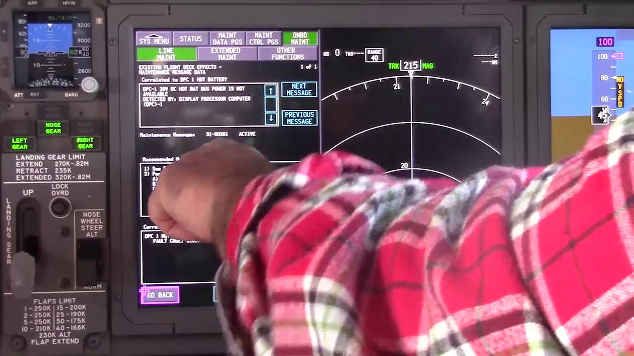
Current status, fault history, autotest, interactive tests and surface tests answer different questions. History can preserve what was detected around a past event; a current test may pass after the condition disappears. The chapter specifically exposes maintenance monitors, suspect LRUs and interface information to guide IFIM work. The technician’s job is to correlate that evidence with the reported flight condition, channel, mode and physical response rather than treating “BITE passed” as proof that no intermittent problem existed.
Technician evidence matrix
Record selected/armed/active modes, FCC channel, required sensor/navigation inputs, downstream control authority, physical response and BITE current/history evidence.
Before using a maintenance message as a conclusion, note what independent evidence agrees with it and what evidence does not. If an alternate source, channel or display changes the symptom, record that explicitly because it can separate a common path from a source-specific path. Preserve configuration and event conditions in the handover so the next technician does not have to rebuild the diagnostic context from memory.
Evidence-first study method
For any system complaint, separate source/input, control logic, physical response, sensing/indication and consumer/result. When two layers disagree, that disagreement is useful evidence. Do not turn that evidence into a maintenance action until the applicable approved fault-isolation or maintenance data is open.
Approved-data boundary
Educational system explanation only. Do not use this page to perform maintenance, operate aircraft systems, isolate components or determine dispatch status. Current approved maintenance data, aircraft effectivity and operator procedures control real aircraft work.