Educational familiarization only. This TechOpsBase resource is an original learning transformation grounded in a privately supplied B737 MAX ATA 24 source. It does not reproduce manufacturer task steps, limits, figures or controlled maintenance instructions. Current approved data and aircraft effectivity control real work.
What this resource teaches
Understand how engine-driven generation becomes controlled aircraft AC power and why source quality matters before a bus is energized.
Generation begins with mechanical input
The chapter identifies integrated drive generators (IDGs) as principal engine-driven AC sources. The useful learning idea is energy conversion: engine mechanical power drives a generator, while the drive/generator control architecture keeps the electrical output within the usable system envelope.
Control and protection sit between source and bus
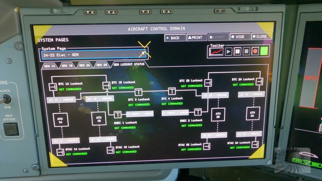
Generator-control hardware evaluates source condition and controls connection to the distribution system. A generator can be rotating without being accepted as a valid bus source. That distinction is central to electrical troubleshooting.
APU and external power are alternative sources
ATA 24 includes APU electrical supply and external power. Treat these as alternative ways to energize aircraft buses, each with its own availability and acceptance/control path.
Source availability is not the same as bus power
A source can be healthy at its output while a downstream contactor, control decision or bus path prevents the load from receiving power. Conversely, a dead source does not automatically mean every downstream bus is dead if another source can feed it.
Evidence hierarchy
When diagnosing a power complaint conceptually, distinguish: source producing power ? source accepted by control/protection ? connection path closed ? target bus energized ? local load powered.
Put this topic into the wider system
Generated, converted and stored energy are different
IDG/APU/external sources provide or deliver AC energy, TRUs convert AC to DC, and the battery stores energy. Keeping those roles distinct helps explain why an apparently DC-only symptom can have an upstream AC cause and why standby power can depend on conversion between domains.
Source substitution is diagnostic evidence
Multiple AC sources let maintenance distinguish source-specific problems from common distribution problems. If one accepted source powers a bus correctly while another does not, the hypothesis shifts upstream toward the failed source or its control/connection path. If no source can power the same bus, the shared distribution path deserves more attention.
Deeper system reasoning
Separate generation, conversion and storage
ATA 24 contains AC generation, transformer-rectifier units, batteries/chargers and standby power. Those are different energy roles. IDG/APU/external sources provide AC power; TRUs convert AC to DC; batteries store DC energy; standby architecture selects or converts sources so essential loads can remain powered. This separation matters because a DC symptom can originate in AC supply or conversion, while a standby complaint can involve battery condition, static-inverter/SPCU logic, or the normal source path rather than one simple “battery problem.”
Bus-level symptoms are often more informative than component names
When several unrelated loads disappear together, look for their shared bus or upstream connection before treating each load as a separate failure. When one local load fails but neighboring loads on the same bus remain normal, reason downstream toward local protection, wiring or the load. The chapter’s bus-tie, power-distribution, BPCU and load-shed content supports this architecture-first approach. Wiring diagrams and approved fault isolation remain necessary to identify the actual circuit and allowed actions.
Technician evidence matrix
Record active/available sources, which bus/load group is affected, whether an alternate source changes the symptom, conversion/battery state and whether the indication agrees with actual load operation.
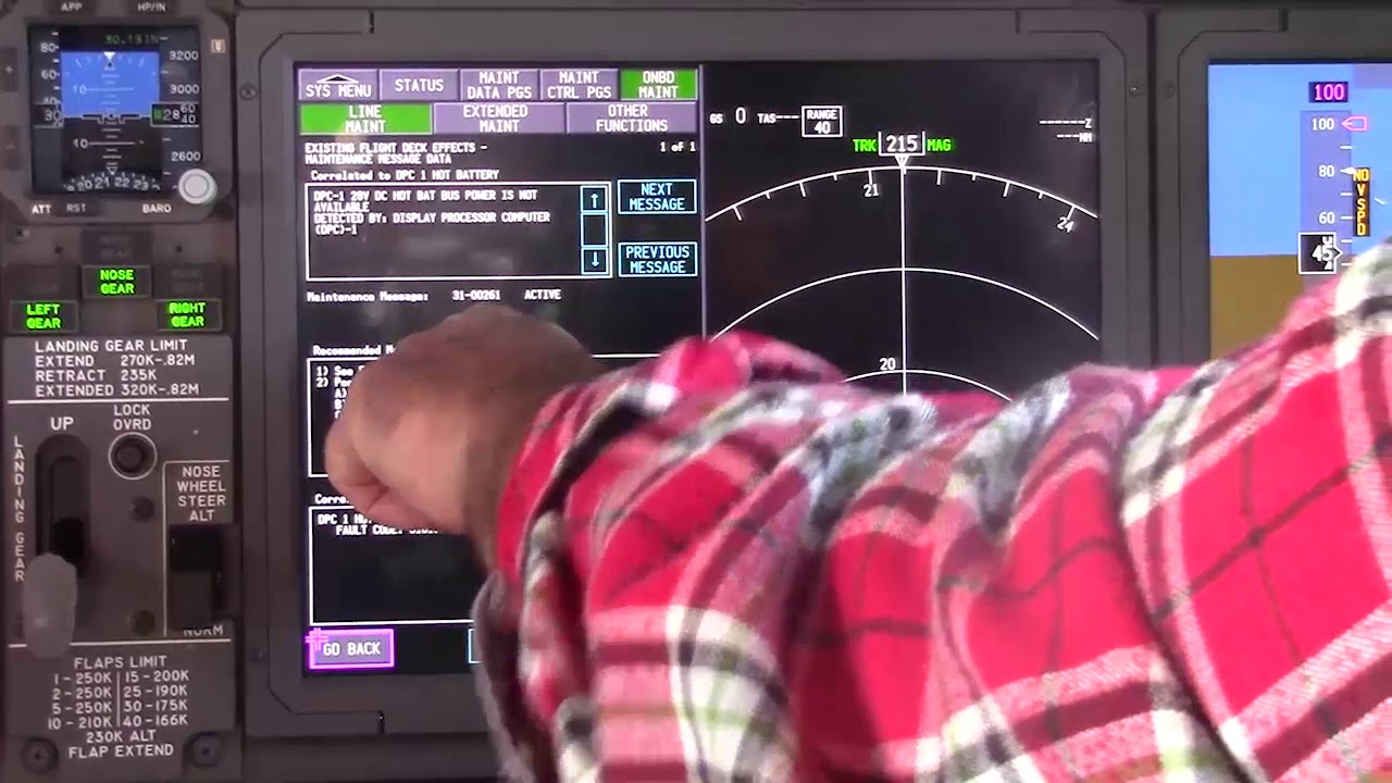
Before using a maintenance message as a conclusion, note what independent evidence agrees with it and what evidence does not. If an alternate source, channel or display changes the symptom, record that explicitly because it can separate a common path from a source-specific path. Preserve configuration and event conditions in the handover so the next technician does not have to rebuild the diagnostic context from memory.
Evidence-first study method
For any system complaint, separate source/input, control logic, physical response, sensing/indication and consumer/result. When two layers disagree, that disagreement is useful evidence. Do not turn that evidence into a maintenance action until the applicable approved fault-isolation or maintenance data is open.
Approved-data boundary
Educational system explanation only. Do not use this page to perform maintenance, operate aircraft systems, isolate components or determine dispatch status. Current approved maintenance data, aircraft effectivity and operator procedures control real aircraft work.