Educational familiarization only. This TechOpsBase resource is an original learning transformation grounded in a privately supplied B737 MAX ATA 21 source. It does not reproduce manufacturer task steps, limits, figures or controlled maintenance instructions. Current approved data and aircraft effectivity control real work.
What this resource teaches
Learn the cabin-pressure control loop without turning a learning page into an operational or maintenance procedure.
Pressure is controlled by managing outflow
Cabin pressure is not “made” by the outflow valve. Conditioned air enters the pressure vessel and the outflow path regulates how quickly air leaves. Controlling outflow controls the pressure differential and cabin-altitude behavior.
Controllers and valve actuation
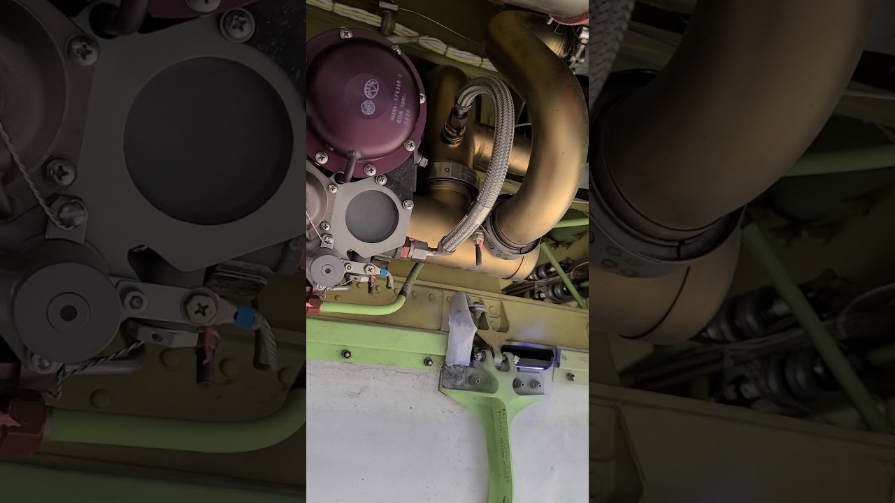
The chapter includes cabin-pressure controllers and outflow-valve components. Learn them as a control chain: pressure-related inputs ? controller computation ? outflow-valve command ? valve movement ? cabin-pressure response.
Automatic and alternate capability
Redundant/control alternatives exist so that a single failure does not automatically remove all pressure-control capability. The exact switching and dispatch rules are configuration- and procedure-dependent, so the learning goal is to recognize the layers rather than memorize a task.
Indication versus real pressure state
A displayed cabin-pressure value depends on sensing, processing and display. A valve-position indication depends on a different chain. When symptoms conflict, independent evidence becomes important.
Technician reasoning
Classify whether the evidence points toward supply air, pressure sensing, controller logic, valve actuation or the pressure vessel/outflow path. Then use approved fault isolation to discriminate between those branches.
Put this topic into the wider system
Cross-system interfaces
ATA 21 touches ATA 36 pneumatic supply, ATA 24 electrical power, ATA 31 display/maintenance data and several smoke/protection functions. A symptom that crosses those boundaries should be mapped by shared source and control dependencies rather than by ATA number alone.
Upstream/downstream boundary
ATA 21 is highly dependent on ATA 36. When cabin airflow or cooling is weak, treat pneumatic source condition and pack/air-conditioning condition as separate hypotheses. Once conditioned air exists, distribution, recirculation, local trim demand and sensing become downstream branches. This simple boundary is valuable because it prevents replacing an ATA 21 component for an upstream air-supply problem.
Deeper system reasoning
Pack performance needs both flow and heat rejection
The pack material supports a useful distinction between having airflow and achieving cooling. Ram-air and heat-exchanger performance provide the heat-rejection side of the process; pack flow/control provides the mass-flow side. A technician evaluating weak cooling should therefore capture conditions that change heat rejection as well as the commanded pack state. The same hardware can appear to perform differently on the ground and in flight because the thermal environment and ram-air conditions are different.
Technician evidence matrix
Record the affected zone/function, pneumatic source condition, pack/flow state, temperature demand versus sensed result, recirculation/equipment-cooling status and pressure-control evidence.
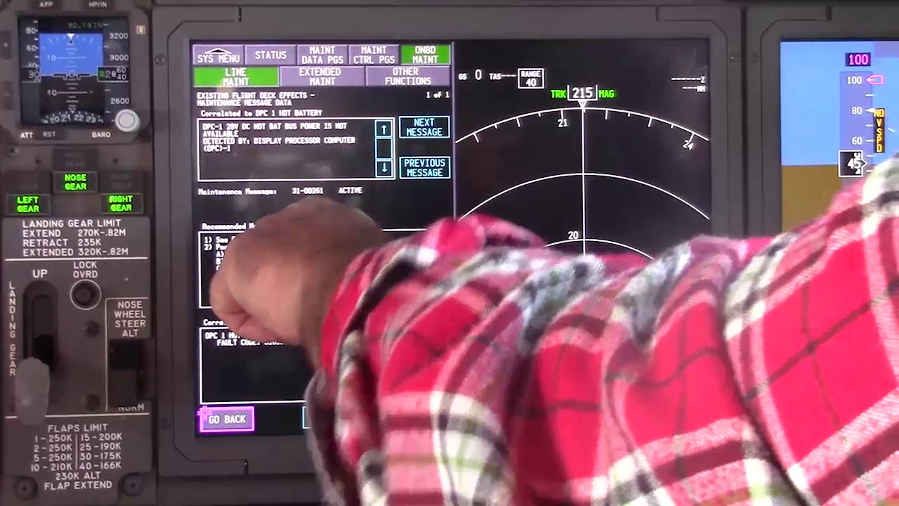
Before using a maintenance message as a conclusion, note what independent evidence agrees with it and what evidence does not. If an alternate source, channel or display changes the symptom, record that explicitly because it can separate a common path from a source-specific path. Preserve configuration and event conditions in the handover so the next technician does not have to rebuild the diagnostic context from memory.
Evidence-first study method
For any system complaint, separate source/input, control logic, physical response, sensing/indication and consumer/result. When two layers disagree, that disagreement is useful evidence. Do not turn that evidence into a maintenance action until the applicable approved fault-isolation or maintenance data is open.
Approved-data boundary
Educational system explanation only. Do not use this page to perform maintenance, operate aircraft systems, isolate components or determine dispatch status. Current approved maintenance data, aircraft effectivity and operator procedures control real aircraft work.