Educational familiarization only. This TechOpsBase resource is an original learning transformation grounded in a privately supplied B737 MAX ATA 21 source. It does not reproduce manufacturer task steps, limits, figures or controlled maintenance instructions. Current approved data and aircraft effectivity control real work.
What this resource teaches
Build the complete ATA 21 mental model: pneumatic supply, packs, mixing/distribution, recirculation, zone control and pressurization as related but distinct functions.
Start with the energy source
The cooling packs do not create their own pneumatic energy. ATA 21 maintenance material explicitly relies on a pressurized pneumatic supply, so the first useful boundary is between ATA 36 source air and ATA 21 conditioning. That prevents a weak-air-supply problem from being mistaken for a pack-only problem.
Conditioning is a chain, not one box
A useful learning path is source air ? pack flow/control ? heat removal and air-cycle cooling ? conditioned-air distribution ? zone demand. Each stage can be healthy while a downstream stage is not, so “the pack is on” is not proof that the cabin is receiving the intended result.
Distribution and recirculation matter
Cabin comfort depends on where conditioned air goes and how recirculated air is blended. Recirculation can reduce pack demand while distribution ducting determines which zones actually receive the air. A temperature complaint therefore has a source side, a conditioning side and a distribution side.
Pressurization is related but functionally separate
The cabin-pressure control system uses cabin-pressure controllers and the outflow-valve path to control cabin pressure. It shares the overall environmental-control context but should not be mentally collapsed into temperature control.
Technician reasoning
When a symptom is reported, first classify it: airflow quantity, temperature, equipment cooling or pressure. Then ask whether the upstream pneumatic source and the local ATA 21 function agree. This framing reduces random component chasing.
Put this topic into the wider system
Thermal condition changes the evidence
Cooling performance is influenced by heat load and the ability to reject heat. Ground operation, airflow around heat exchangers, cabin load and the state of recirculation can change the observed result even when the same hardware is installed. A useful technical note therefore records conditions as well as indications.
Display evidence is one layer
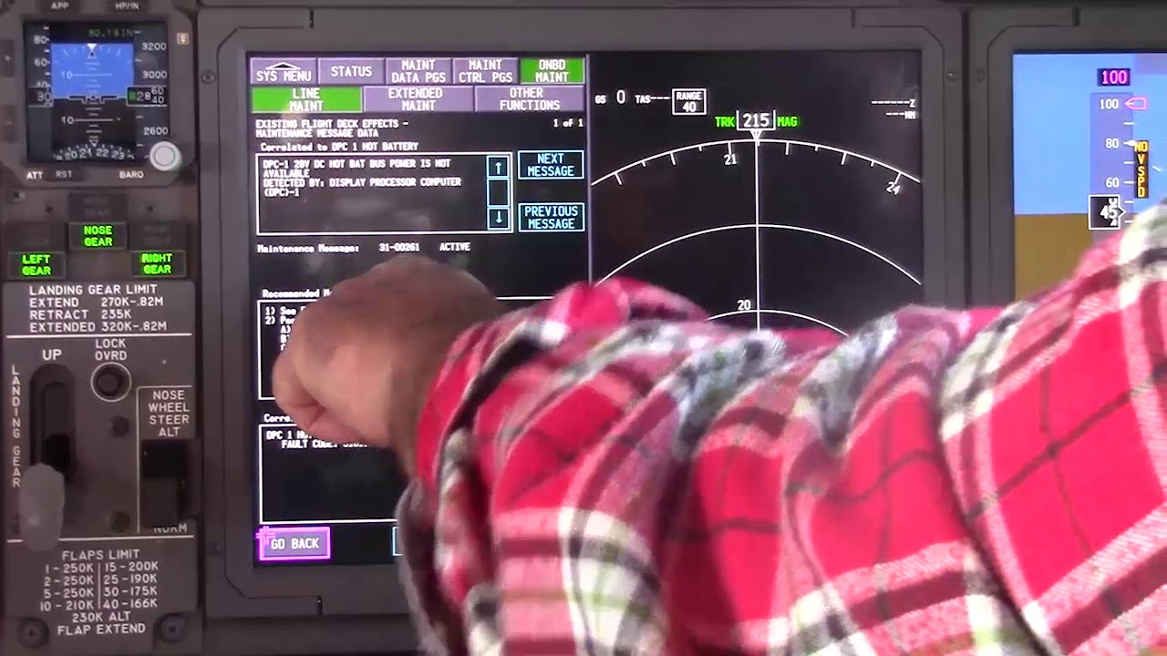
Pack, temperature and pressure indications depend on sensors, controller logic and display paths. Compare the displayed state with independent physical or maintenance-data evidence before deciding whether the indication describes the real air/temperature/pressure condition.
Deeper system reasoning
Pressurization and equipment cooling deserve separate branches
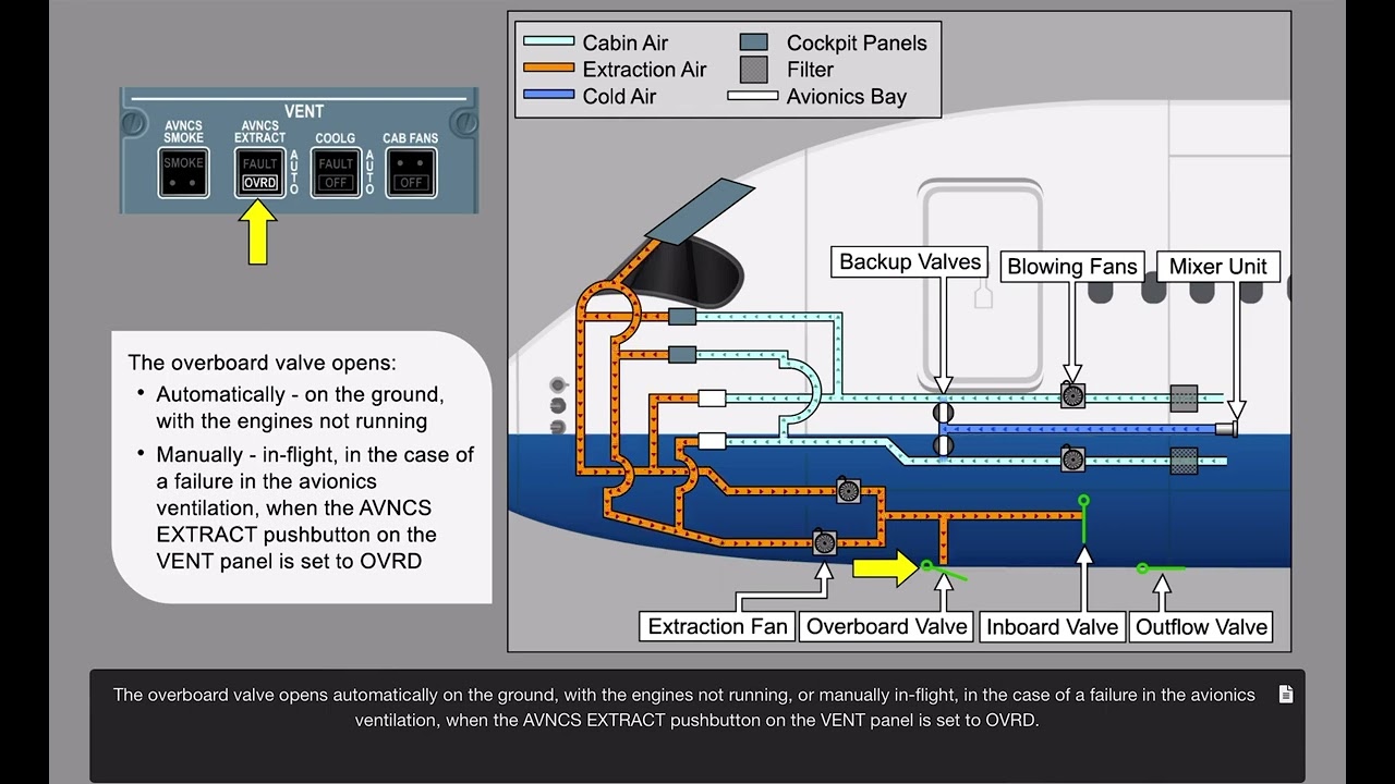
The chapter includes cabin-pressure controllers and outflow-valve control as well as equipment-cooling fans and airflow paths. Both sit inside ATA 21, but their physics and evidence are different. Cabin pressure is a mass-balance/control problem involving inflow and controlled outflow; equipment cooling is a local ventilation/heat-removal problem. Keeping those branches separate makes mixed symptoms easier to interpret and prevents a broad ATA label from hiding the actual function being diagnosed.
Follow the airflow in layers
For study, trace ATA 21 in layers rather than as one environmental-control box. Begin with usable source air entering the pack. Then follow flow-control and cooling, the mix/distribution path, recirculation contribution, zone-temperature demand and finally cabin-pressure control as a related but separate function. The supplied chapter also treats equipment cooling as its own airflow problem. This layered view explains why a cabin complaint can be caused upstream by air supply, inside the cooling pack, downstream in distribution, or in sensing/control without those being the same failure mode.
Technician evidence matrix
Record the affected zone/function, pneumatic source condition, pack/flow state, temperature demand versus sensed result, recirculation/equipment-cooling status and pressure-control evidence.
Before using a maintenance message as a conclusion, note what independent evidence agrees with it and what evidence does not. If an alternate source, channel or display changes the symptom, record that explicitly because it can separate a common path from a source-specific path. Preserve configuration and event conditions in the handover so the next technician does not have to rebuild the diagnostic context from memory.
Evidence-first study method
For any system complaint, separate source/input, control logic, physical response, sensing/indication and consumer/result. When two layers disagree, that disagreement is useful evidence. Do not turn that evidence into a maintenance action until the applicable approved fault-isolation or maintenance data is open.
Approved-data boundary
Educational system explanation only. Do not use this page to perform maintenance, operate aircraft systems, isolate components or determine dispatch status. Current approved maintenance data, aircraft effectivity and operator procedures control real aircraft work.