Educational familiarization only. This original TechOpsBase lesson does not reproduce manufacturer pages, proprietary figures, maintenance procedures, numerical limits or controlled task data. Actual aircraft work requires current approved data, correct effectivity, operator procedures, authorization, safety controls and supervision.
Resource profile
- Aircraft: Airbus A350 family
- ATA: 49 - Airborne Auxiliary Power
- Audience: Enthusiasts, students, junior technicians and professionals
- Level: Intermediate-to-advanced
- Status: Draft pending technical review
Learning objectives
- Trace APU load paths.
- Explain vibration isolation.
- Recognize redundancy and hidden degradation.
- Diagnose installation vibration.
- Inspect mounts during APU access/removal.
1. Purpose and system role
The suspension holds the APU in alignment under aircraft and engine loads while reducing vibration transmitted to the tailcone. Alignment protects intake, exhaust, fuel, oil, electrical and pneumatic interfaces.
2. Architecture and energy flow
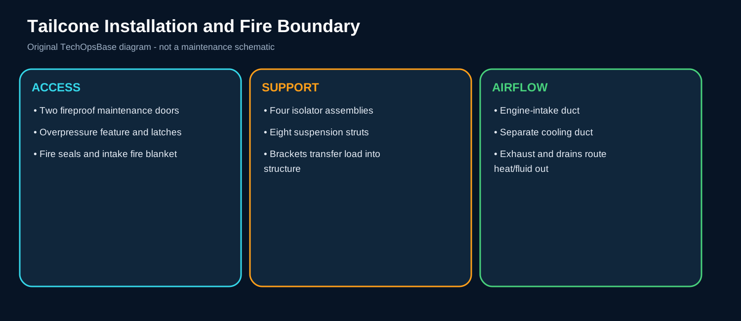
Four isolator assemblies support the APU through eight suspension struts and structural brackets.
Loads travel between the APU frames and the fireproof/overhead tailcone structure.
A fail-safe feature provides a redundant load path at a critical mount, preventing immediate release after one element fails.
3. Major components
Isolators. Provide stiffness and damping between APU and structure. In normal service, the component must perform its role while the ECB or related aircraft system monitors command, feedback or the effect it produces. A defect may be electrical, mechanical, pneumatic, fuel-powered or caused by installation. Useful maintenance evidence includes hardening, cracking, separation, fluid contamination and displacement. The technician should separate the command path from the actual physical response before replacing the component.
Struts. Carry loads along defined axes. In normal service, the component must perform its role while the ECB or related aircraft system monitors command, feedback or the effect it produces. A defect may be electrical, mechanical, pneumatic, fuel-powered or caused by installation. Useful maintenance evidence includes bending, looseness, rod-end play, corrosion and witness marks. The technician should separate the command path from the actual physical response before replacing the component.
APU brackets. Transfer loads into APU frames. In normal service, the component must perform its role while the ECB or related aircraft system monitors command, feedback or the effect it produces. A defect may be electrical, mechanical, pneumatic, fuel-powered or caused by installation. Useful maintenance evidence includes cracks at fasteners, fretting and distortion. The technician should separate the command path from the actual physical response before replacing the component.
Aircraft brackets. React loads into tailcone structure. In normal service, the component must perform its role while the ECB or related aircraft system monitors command, feedback or the effect it produces. A defect may be electrical, mechanical, pneumatic, fuel-powered or caused by installation. Useful maintenance evidence includes fastener condition, cracks and local structural damage. The technician should separate the command path from the actual physical response before replacing the component.
Redundant mount elements. Maintain support after one-element failure. In normal service, the component must perform its role while the ECB or related aircraft system monitors command, feedback or the effect it produces. A defect may be electrical, mechanical, pneumatic, fuel-powered or caused by installation. Useful maintenance evidence includes independent hardware condition and correct load sharing. The technician should separate the command path from the actual physical response before replacing the component.
4. Normal operation
Step 1: Start/stop
Torque reversals and speed changes excite the suspension.
Step 2: Governed operation
Isolators reduce continuous rotating vibration.
Step 3: Generator/bleed load
Changed shaft torque can expose mount looseness or internal vibration.
Step 4: Shutdown/coast-down
Changing frequency helps separate contact from imbalance.
5. Control, monitoring and protection
The ECB can record speed/shutdown events but cannot measure isolator stiffness directly.
Vibration diagnosis needs phase, load, location and physical inspection.
6. Failure modes and maintenance reasoning
- Hardened isolator: Higher cabin/tailcone vibration without obvious displacement.
- Soft/separated isolator: Excess motion, alignment shift and component contact.
- Loose strut/bracket: Fretting, witness marks and load transfer into neighbors.
- Misalignment: Stress at intake, exhaust, lines and connectors.
- Internal rotating fault: Vibration remains after mount/contact checks and may include debris or oil heat.
7. Interfaces with other aircraft systems
- Exhaust bellows and supports.
- Intake duct and plenum alignment.
- Fuel, oil and electrical flexible connections.
- Tailcone structural attachment.
- Oil/debris monitoring for internal faults.
8. Practical scenarios
Vibration only under bleed load
Check load-compressor/power-section behavior as well as mounts.
Vibration after exhaust replacement
Inspect contact, alignment, supports and bellows before internal APU removal.
Fluid on isolator
Find the leak and assess material degradation, not only mount security.
9. Technician takeaways
- Fail-safe does not mean maintenance-free.
- Compare symmetrical mount locations.
- Document witness marks before cleaning.
- Verify clearances after any suspension work.
Maintenance boundary
This resource teaches architecture, operating logic and troubleshooting reasoning. It excludes task steps, torque values, test limits, servicing quantities, start thresholds and dispatch decisions. The APU contains hot surfaces, rotating machinery, high-energy start circuits, pressurized fuel and oil, automatically moving components and fire-system interfaces. Use current approved AMM/TSM/WDM data and all required isolation procedures.
Review prompts
- What service should the subsystem provide?
- Which component creates the output and which component controls it?
- Which sensor or feedback proves the result?
- What is the command-versus-response evidence?
- Which ground/flight protection logic applies?
- Which other ATA system supplies or receives the command?
- What physical evidence should be preserved before reset?
- What heat, rotation, pressure, electrical or fire-boundary hazard remains?