Educational familiarization only. This TechOpsBase resource is an original learning transformation grounded in a privately supplied B737 MAX ATA 28 source. It does not reproduce manufacturer task steps, limits, figures or controlled maintenance instructions. Current approved data and aircraft effectivity control real work.
What this resource teaches
Trace fuel from main/center tanks through boost-pump and manifold paths toward engines and APU without copying the manufacturer schematic.
Three storage regions drive the basic map
The supplied chapter repeatedly distinguishes No. 1 main tank, No. 2 main tank and center-tank functions. Start with those storage regions before studying pumps and valves.
Feed requires pressure and an open path
Boost pumps provide motive pressure while valves and manifolds define the route toward engine/APU consumers. A pump running cannot feed a consumer through a closed or blocked path; an open path cannot create pressure by itself.
Crossfeed changes connectivity
The crossfeed path lets left/right feed manifolds be connected under defined conditions. Conceptually, this separates “which tank/pump is producing pressure?” from “which manifold/engine can receive it?”
APU is another consumer of the fuel-feed network
The chapter includes APU fuel shutoff/feed relationships. This gives a useful cross-system link to ATA 49 without turning ATA 28 into an APU-operating procedure.
Evidence-first reasoning
For a feed complaint: tank quantity ? pump/source state ? valve/path state ? manifold pressure/functional result ? indication. Approved fault isolation then determines the actual next test.
Put this topic into the wider system
Cross-system dependencies
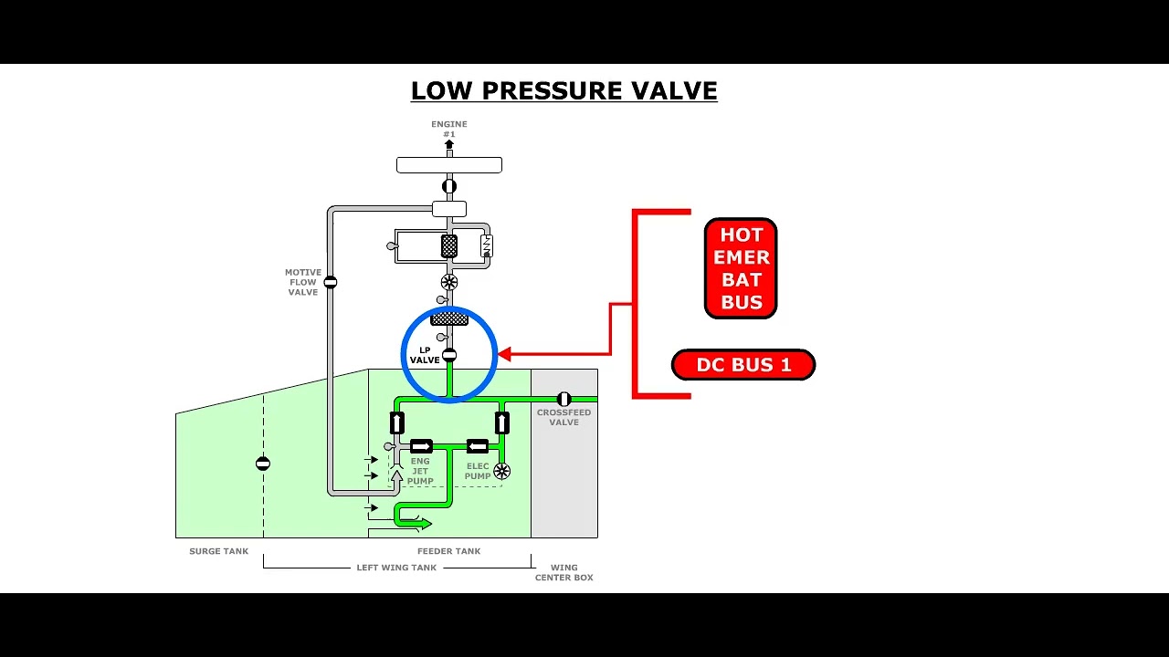
ATA 28 depends on ATA 24 electrical power for pumps/control, interfaces with ATA 49 for APU feed, and shares the center-tank safety objective with ATA 47. Treat these interfaces as part of the system map when symptoms appear in more than one chapter.
Source, path and consumer must all agree
Fuel feed is easiest to reason about when pressure source, routing valves/manifold and final consumer are separate layers. A running boost pump is not enough if the inlet is starved or the path is isolated; an open crossfeed does not create pressure; a consumer complaint does not identify the failed layer.
Deeper system reasoning
Pump assignment and crossfeed create comparison opportunities
The supplied chapter identifies forward and aft boost pumps in each main tank plus left and right center-tank pumps, and it includes crossfeed-valve testing. That architecture provides natural comparison points: left versus right, main versus center, local feed versus crossfeed. If a symptom moves when the source/path configuration changes, that change is evidence. If the symptom remains tied to the same consumer or manifold section, the hypothesis should move accordingly.
Center-tank logic adds automatic behavior
Center-tank feed is not simply another pair of manually controlled pumps. The source includes automatic shutoff logic and fuel-scavenge behavior, so pump indication, quantity state and system configuration have to be interpreted together. Scavenge also creates a flow relationship between center-tank residual fuel and a main-tank path. This is why a quantity trend can be useful evidence even when the immediate complaint appears to be a pump or feed issue.
Technician evidence matrix
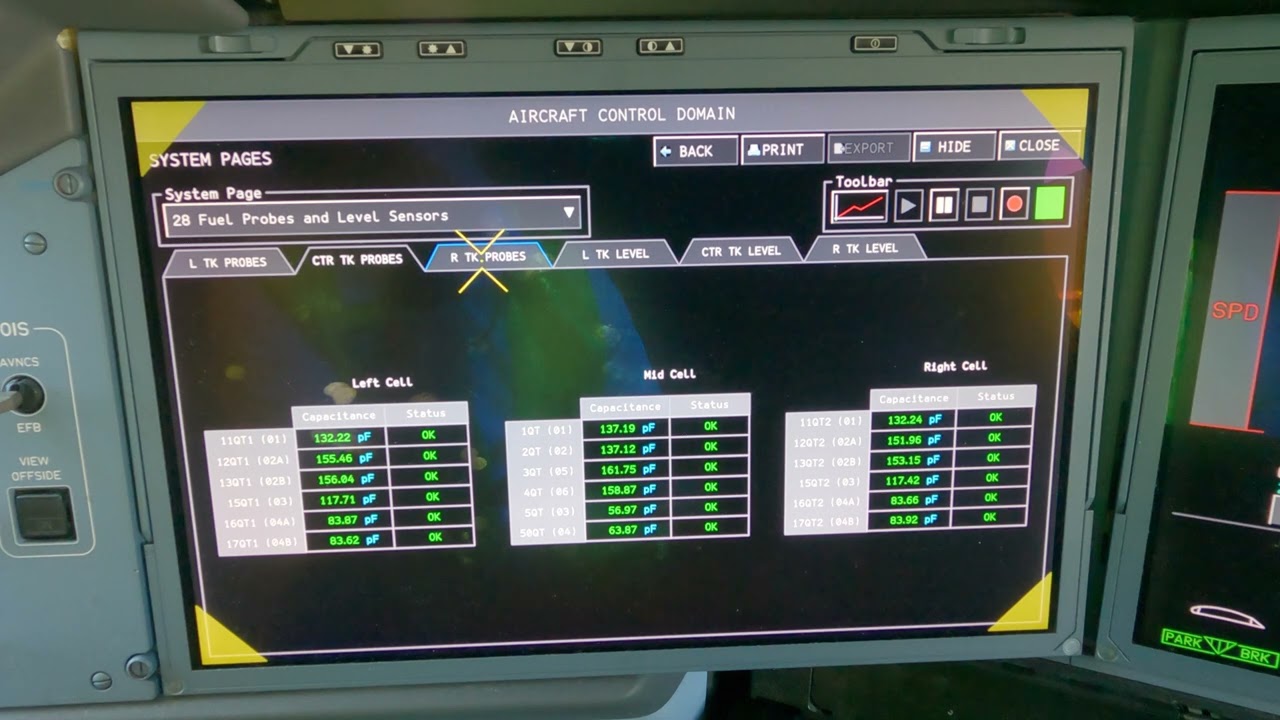
Record tank quantity, expected pump/source, valve/manifold connectivity, affected consumer, crossfeed configuration and whether the symptom follows the source or remains with the path/consumer.
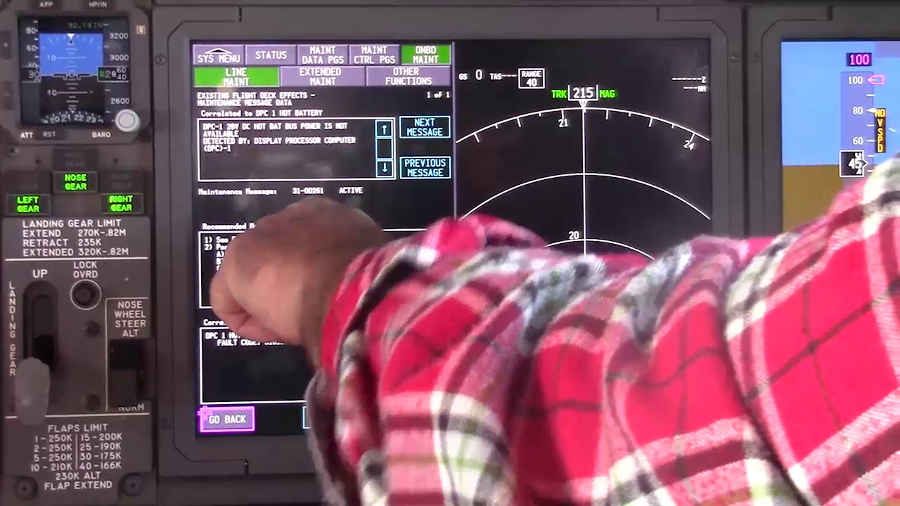
Before using a maintenance message as a conclusion, note what independent evidence agrees with it and what evidence does not. If an alternate source, channel or display changes the symptom, record that explicitly because it can separate a common path from a source-specific path. Preserve configuration and event conditions in the handover so the next technician does not have to rebuild the diagnostic context from memory.
Evidence-first study method
For any system complaint, separate source/input, control logic, physical response, sensing/indication and consumer/result. When two layers disagree, that disagreement is useful evidence. Do not turn that evidence into a maintenance action until the applicable approved fault-isolation or maintenance data is open.
Approved-data boundary
Educational system explanation only. Do not use this page to perform maintenance, operate aircraft systems, isolate components or determine dispatch status. Current approved maintenance data, aircraft effectivity and operator procedures control real aircraft work.