Educational familiarization only. This TechOpsBase resource is an original learning transformation grounded in a privately supplied B737 MAX ATA 47 source. It does not reproduce manufacturer task steps, limits, figures or controlled maintenance instructions. Current approved data and aircraft effectivity control real work.
What this resource teaches
Understand why the NGS exists and trace source air through conditioning, separation and NEA distribution to the center tank.
Purpose first
The supplied AMM describes the NGS as a system that reduces center-tank flammability. Fresh air contains mostly nitrogen plus oxygen; the system separates the streams so nitrogen-enriched air (NEA) can be routed to the tank environment.
It is an onboard separation process
The architecture includes an air separation module (ASM), so the aircraft is not merely storing a fixed bottle of nitrogen. It conditions a source airflow and separates it into nitrogen-enriched and oxygen-enriched streams.
Distribution reaches the center tank
The NEA distribution system (NEADS) runs from the ASM toward the center tank and includes check-valve/flame-arresting features. This creates a physical protective path with its own leak and integrity requirements.
ATA 21/36 provide important upstream context
The NGS sits in the environmental-control area and uses pneumatic/conditioned-air relationships. Its source path therefore links naturally with ATA 36 and ATA 21.
ATA 28 is the protected system
ATA 47 is not a fuel-feed system, but its reason for existing is directly tied to center-tank fuel-vapor flammability. That is why ATA 28 and ATA 47 should be learned together.
Put this topic into the wider system
Air quality is part of system performance
The NGS does not only need airflow. Temperature, cleanliness, pressure and contamination state influence the separation module. This is why filter, heat exchanger, temperature protection and contamination precautions belong in the functional model rather than a separate housekeeping chapter.
Protection path and indication path are separate
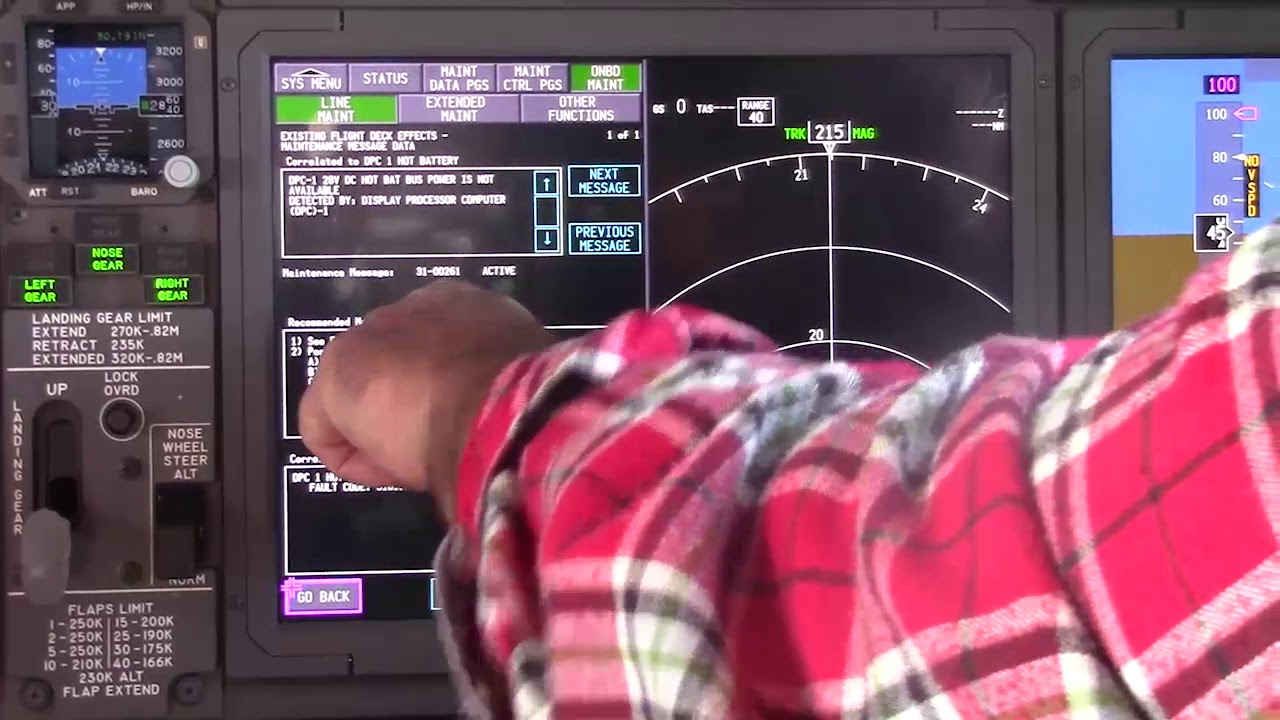
The controller can use altitude, oxygen, pressure, temperature and differential-pressure information to supervise the system. A maintenance indication is therefore the end of a sensing and logic chain; it should be compared with the expected physical airflow/separation/distribution state.
Deeper system reasoning
Generation and distribution are two different success criteria
Producing nitrogen-enriched air does not guarantee the protected tank receives it. NEADS tubing, backflow prevention, cross-vent/check valves, flame arresting and leak integrity form the distribution branch. The chapter includes dedicated leak checks of the NEADS path. Therefore a healthy generation/BITE indication should not automatically clear the distribution side when tank-protection performance or leakage evidence suggests otherwise.
Sensors and BITE form an observation layer
Altitude, oxygen, pressure, temperature and differential-pressure sensing feed the control/monitoring picture, while the BITE display and operability indication expose system status to maintenance. These are observation/control layers, not the physical separation process itself. If sensor/BITE evidence conflicts with airflow or distribution evidence, preserve that disagreement and use approved fault isolation. ATA 47 also crosses ATA 36/21 for source-air conditioning and ATA 28 for the center-tank safety objective.
Technician evidence matrix
Record source-air availability, conditioning/filter state, temperature/pressure/oxygen indications, ASM/NEADS status and whether tank-protection/BITE evidence points to generation or distribution.
Before using a maintenance message as a conclusion, note what independent evidence agrees with it and what evidence does not. If an alternate source, channel or display changes the symptom, record that explicitly because it can separate a common path from a source-specific path. Preserve configuration and event conditions in the handover so the next technician does not have to rebuild the diagnostic context from memory.
Evidence-first study method
For any system complaint, separate source/input, control logic, physical response, sensing/indication and consumer/result. When two layers disagree, that disagreement is useful evidence. Do not turn that evidence into a maintenance action until the applicable approved fault-isolation or maintenance data is open.
Approved-data boundary
Educational system explanation only. Do not use this page to perform maintenance, operate aircraft systems, isolate components or determine dispatch status. Current approved maintenance data, aircraft effectivity and operator procedures control real aircraft work.