Educational familiarization only. This original TechOpsBase lesson does not reproduce manufacturer pages, proprietary figures, maintenance procedures, numerical limits or controlled task data. Actual aircraft work requires current approved data, correct effectivity, operator procedures, authorization, safety controls and supervision.
Resource profile
- Aircraft: Airbus A350 family
- ATA: 49 - Airborne Auxiliary Power
- Audience: Enthusiasts, students, junior technicians and professionals
- Level: Intermediate-to-advanced
- Status: Draft pending technical review
Learning objectives
- Describe the tailcone installation.
- Explain door and fire-boundary functions.
- Recognize hidden seal degradation.
- Connect access, airflow and drain safety.
- Restore the compartment correctly.
1. Purpose and system role
The installation supports the APU, contains heat and fire, routes intake/cooling/exhaust airflow and provides safe maintenance access. The compartment is part of the APU protection system, not just a space around the engine.
2. Architecture and energy flow
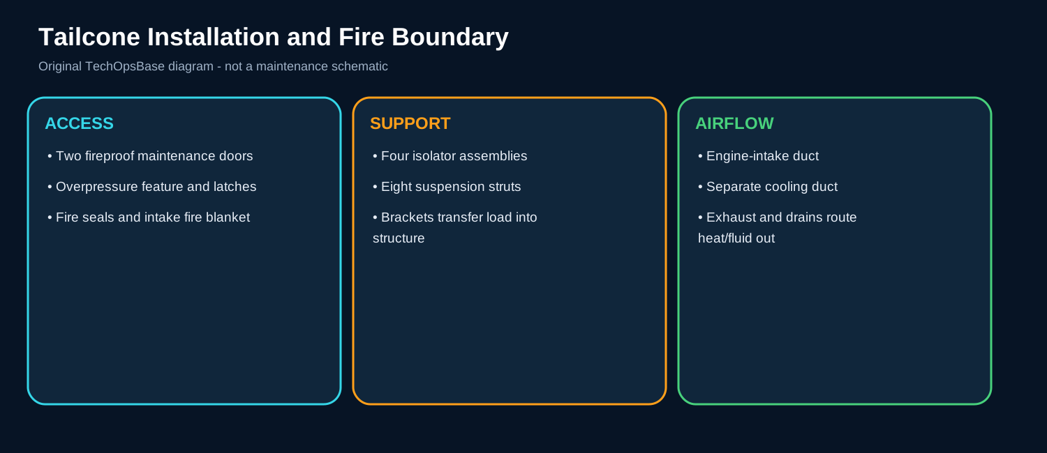
Two manually operated fireproof doors provide access. Hinges, latches, locking features and hold-open devices must remain serviceable.
An overpressure feature provides controlled relief and is linked to the access/locking arrangement.
Firewalls, perimeter seals, duct seals and an intake fire blanket close gaps around large penetrations while allowing movement.
3. Major components
Maintenance doors. Provide fireproof access and structural closure. In normal service, the component must perform its role while the ECB or related aircraft system monitors command, feedback or the effect it produces. A defect may be electrical, mechanical, pneumatic, fuel-powered or caused by installation. Useful maintenance evidence includes latch engagement, alignment, seal compression, cracks and hold-open security. The technician should separate the command path from the actual physical response before replacing the component.
Overpressure feature. Relieves abnormal compartment pressure through a controlled path. In normal service, the component must perform its role while the ECB or related aircraft system monitors command, feedback or the effect it produces. A defect may be electrical, mechanical, pneumatic, fuel-powered or caused by installation. Useful maintenance evidence includes freedom of movement, locking relationship and structural condition. The technician should separate the command path from the actual physical response before replacing the component.
Fire seals. Limit flame and hot-gas propagation at doors and penetrations. In normal service, the component must perform its role while the ECB or related aircraft system monitors command, feedback or the effect it produces. A defect may be electrical, mechanical, pneumatic, fuel-powered or caused by installation. Useful maintenance evidence includes tears, hardening, compression set, fluid saturation and gaps. The technician should separate the command path from the actual physical response before replacing the component.
Intake fire blanket. Completes the fire boundary around intake geometry. In normal service, the component must perform its role while the ECB or related aircraft system monitors command, feedback or the effect it produces. A defect may be electrical, mechanical, pneumatic, fuel-powered or caused by installation. Useful maintenance evidence includes security, chafing, contamination, overlap and heat damage. The technician should separate the command path from the actual physical response before replacing the component.
Compartment structure. Carries mounts, doors, ducts and fire boundaries. In normal service, the component must perform its role while the ECB or related aircraft system monitors command, feedback or the effect it produces. A defect may be electrical, mechanical, pneumatic, fuel-powered or caused by installation. Useful maintenance evidence includes cracks, distortion, heat discoloration and fastener condition. The technician should separate the command path from the actual physical response before replacing the component.
4. Normal operation
Step 1: Closed condition
Doors and seals maintain aerodynamic and fireproof integrity.
Step 2: APU operation
Cooling airflow and pressure act on doors, drains and seals.
Step 3: Maintenance access
The correct opening sequence releases locks and supports the doors.
Step 4: Restoration
All latches, seals, drains, insulation and foreign-object controls are verified.
5. Control, monitoring and protection
No cockpit parameter directly proves fire-seal condition; visual inspection is the main defense against hidden degradation.
Cooling-air and exhaust leakage can heat doors and seals even when the APU core is healthy.
6. Failure modes and maintenance reasoning
- Uneven seal compression: Door distortion, latch rigging, foreign material or damaged mating surface.
- Heat damage: Exhaust leakage, missing insulation or fire-boundary gap.
- Door cannot open/close: Locking, latch, hinge, overpressure feature or structural interference.
- Fluid-saturated blanket: Upstream fuel/oil leak or drain problem.
- Repeated flap/duct interference: Installation distortion or incorrect restoration.
7. Interfaces with other aircraft systems
- Mounts and structural load paths.
- Air-intake and cooling ducts.
- Exhaust flexible coupling and fire seal.
- Drain lines and door-mounted drain masts.
- ATA 26 APU fire protection.
8. Practical scenarios
Door appears latched but seal gap remains
Inspect the complete latch pattern and mating surface; do not assume a new seal corrects distorted structure.
Local tailcone heat mark
Trace exhaust leakage, missing insulation and fire-seal condition before blaming the power section.
After intake maintenance
Inspect fire blanket, seals, flap clearance and foreign-object control before closure.
9. Technician takeaways
- Physical restoration matters as much as electronic testing.
- A hidden fire-boundary failure may create no operational message.
- Do not use ducts, lines or seals as handholds.
- Control automatic start and hot surfaces before access.
Maintenance boundary
This resource teaches architecture, operating logic and troubleshooting reasoning. It excludes task steps, torque values, test limits, servicing quantities, start thresholds and dispatch decisions. The APU contains hot surfaces, rotating machinery, high-energy start circuits, pressurized fuel and oil, automatically moving components and fire-system interfaces. Use current approved AMM/TSM/WDM data and all required isolation procedures.
Review prompts
- What service should the subsystem provide?
- Which component creates the output and which component controls it?
- Which sensor or feedback proves the result?
- What is the command-versus-response evidence?
- Which ground/flight protection logic applies?
- Which other ATA system supplies or receives the command?
- What physical evidence should be preserved before reset?
- What heat, rotation, pressure, electrical or fire-boundary hazard remains?