Educational familiarization only. This original TechOpsBase lesson does not reproduce manufacturer pages, proprietary figures, maintenance procedures, numerical limits or controlled task data. Actual aircraft work requires current approved data, correct effectivity, operator procedures, authorization, safety controls and supervision.
Resource profile
- Aircraft: Airbus A350 family
- ATA: 49 - Airborne Auxiliary Power
- Audience: Enthusiasts, students, junior technicians and professionals
- Level: Intermediate-to-advanced
- Status: Draft pending technical review
Learning objectives
- Build a safe troubleshooting plan.
- Preserve event evidence.
- Use phase and lost service.
- Work through integrated scenarios.
- Verify complete restoration.
1. Purpose and system role
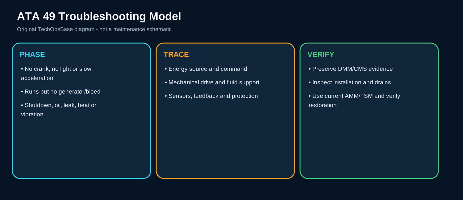
The workshop turns system knowledge into a repeatable maintenance method: define the phase and lost function, control hazards, preserve evidence, trace energy/commands and verify the physical installation.
2. Architecture and energy flow
Troubleshooting begins with start/run/load/shutdown phase and whether the loss is rotation, combustion, electrical, pneumatic, lubrication, cooling or control.
Electronic evidence from ECB/DMM/CMS is combined with physical evidence from drains, sound, vibration, heat, soot, oil and installation.
The final check includes both the repaired function and every affected interface.
3. Major components
Safety isolation. Controls automatic start, electrical, fuel, pneumatic and fire-system hazards. In normal service, the component must perform its role while the ECB or related aircraft system monitors command, feedback or the effect it produces. A defect may be electrical, mechanical, pneumatic, fuel-powered or caused by installation. Useful maintenance evidence includes tags/locks, circuit state, cool-down and access condition. The technician should separate the command path from the actual physical response before replacing the component.
Event record. Captures first fault and sequence. In normal service, the component must perform its role while the ECB or related aircraft system monitors command, feedback or the effect it produces. A defect may be electrical, mechanical, pneumatic, fuel-powered or caused by installation. Useful maintenance evidence includes messages, time, phase, speed/EGT and related systems. The technician should separate the command path from the actual physical response before replacing the component.
Physical inspection. Finds conditions electronic tests cannot see. In normal service, the component must perform its role while the ECB or related aircraft system monitors command, feedback or the effect it produces. A defect may be electrical, mechanical, pneumatic, fuel-powered or caused by installation. Useful maintenance evidence includes leaks, drains, heat, contact, seals, supports and foreign objects. The technician should separate the command path from the actual physical response before replacing the component.
Approved test. Verifies command, response and protection. In normal service, the component must perform its role while the ECB or related aircraft system monitors command, feedback or the effect it produces. A defect may be electrical, mechanical, pneumatic, fuel-powered or caused by installation. Useful maintenance evidence includes current data, correct configuration and restoration. The technician should separate the command path from the actual physical response before replacing the component.
Release review. Confirms complete system and documentation. In normal service, the component must perform its role while the ECB or related aircraft system monitors command, feedback or the effect it produces. A defect may be electrical, mechanical, pneumatic, fuel-powered or caused by installation. Useful maintenance evidence includes operational result, fault closure and physical restoration. The technician should separate the command path from the actual physical response before replacing the component.
4. Normal operation
Step 1: Make safe
Control all energy and movement.
Step 2: Preserve
Save messages and physical evidence before reset/cleaning.
Step 3: Localize
Trace command, feedback, energy and mechanical response.
Step 4: Repair
Correct the initiating cause, not only the reported component.
Step 5: Verify
Test affected function and interfaces.
Step 6: Document
Record cause, evidence and restoration.
5. Control, monitoring and protection
Repeated reset/restart can destroy evidence and create wet/hot-start risk.
A successful electronic test cannot prove correct drains, mounts, duct routing, fire seals or exhaust alignment.
6. Failure modes and maintenance reasoning
- Parts swapping: Replaces reported component without signal-path evidence.
- Cross-ATA blind spot: Ignores aircraft fuel, electrical, bleed or fire interface.
- Evidence loss: Clears DMM/CMS or cleans leak/debris before recording.
- Unsafe reproduction: Repeats surge, hot start or shutdown outside approved test.
- Incomplete restoration: Leaves clamps, seals, drains, doors or safety devices wrong.
7. Interfaces with other aircraft systems
- All ATA 49 subsystems.
- ATA 24, 21/36, 26, 28, 31, 32/34 and 46.
- Maintenance records and component history.
- Physical tailcone installation.
- Operational and safety procedures.
8. Practical scenarios
No crank
Separate command/power/current from mechanical seizure.
Crank no light
Separate ignition, fuel and airflow; inspect drain/exhaust evidence.
Hot/slow start
Compare EGT and speed timing, current, oil and recent work.
Available no generator
Focus on SGCU/generator/distribution after confirming drive.
Available no bleed
Focus on demand, IGV/SCV/bleed, servo fuel and downstream network.
High oil temperature
Trace load, quantity, cooler airflow, bypass and internal wear.
Uncommanded shutdown
Identify protective, emergency, fire, fuel or power-loss path.
Vibration after maintenance
Inspect mounts, exhaust/intake contact and alignment before internal removal.
9. Technician takeaways
- The first fault is often more valuable than the final message.
- Command-versus-response is the core diagnostic comparison.
- Cross-ATA interfaces are common causes.
- Release requires electronic and physical restoration.
Maintenance boundary
This resource teaches architecture, operating logic and troubleshooting reasoning. It excludes task steps, torque values, test limits, servicing quantities, start thresholds and dispatch decisions. The APU contains hot surfaces, rotating machinery, high-energy start circuits, pressurized fuel and oil, automatically moving components and fire-system interfaces. Use current approved AMM/TSM/WDM data and all required isolation procedures.
Review prompts
- What service should the subsystem provide?
- Which component creates the output and which component controls it?
- Which sensor or feedback proves the result?
- What is the command-versus-response evidence?
- Which ground/flight protection logic applies?
- Which other ATA system supplies or receives the command?
- What physical evidence should be preserved before reset?
- What heat, rotation, pressure, electrical or fire-boundary hazard remains?